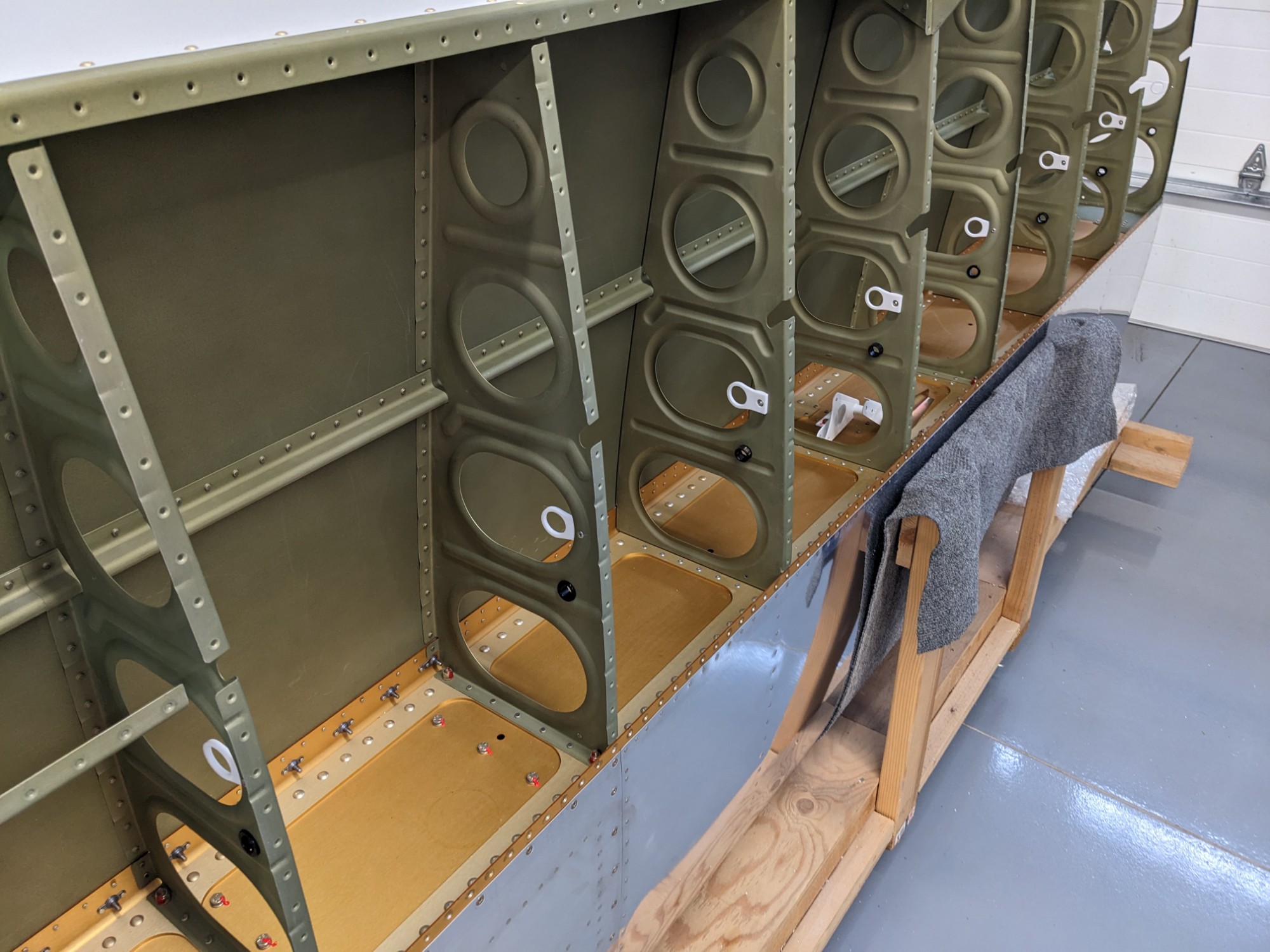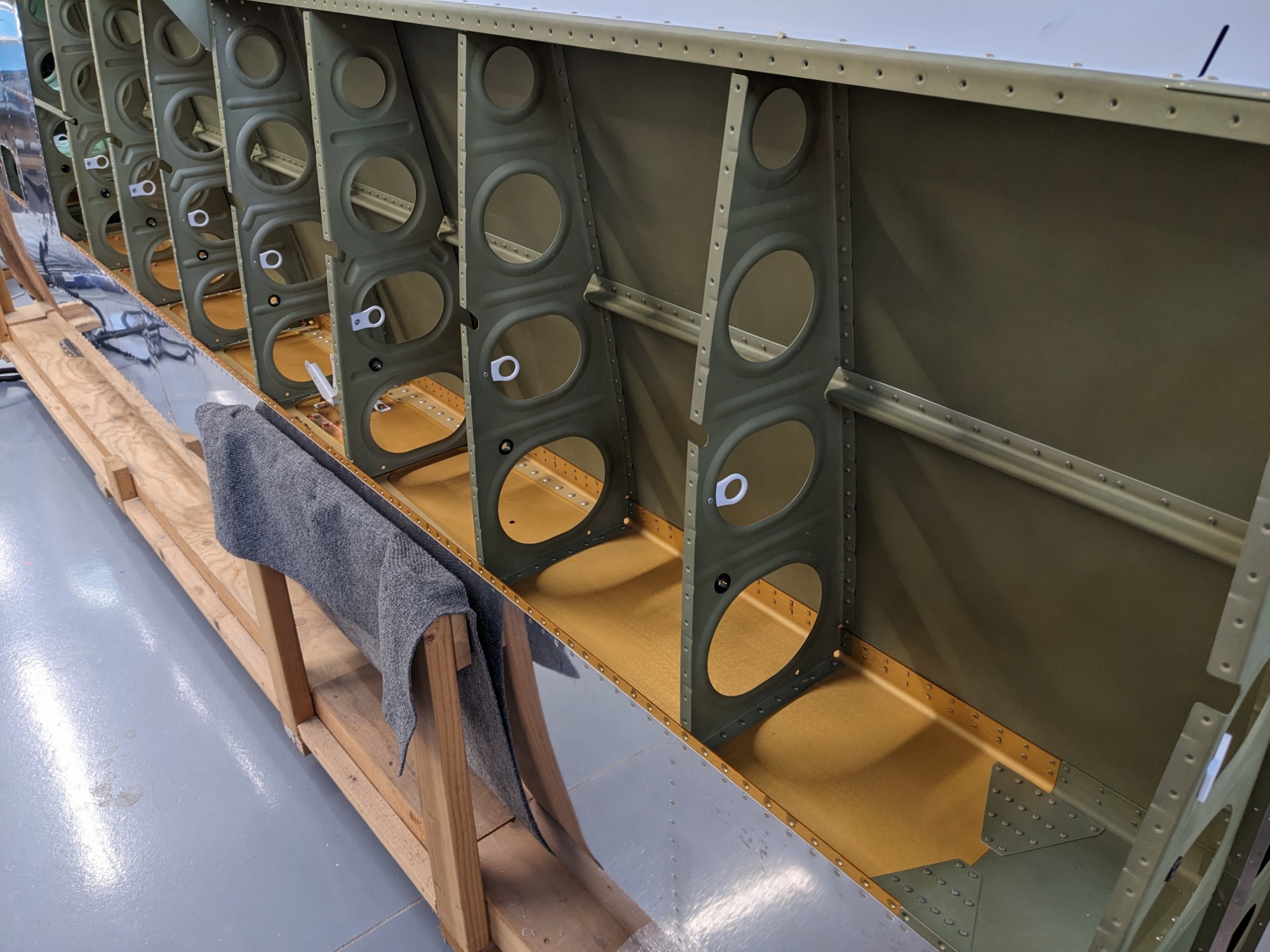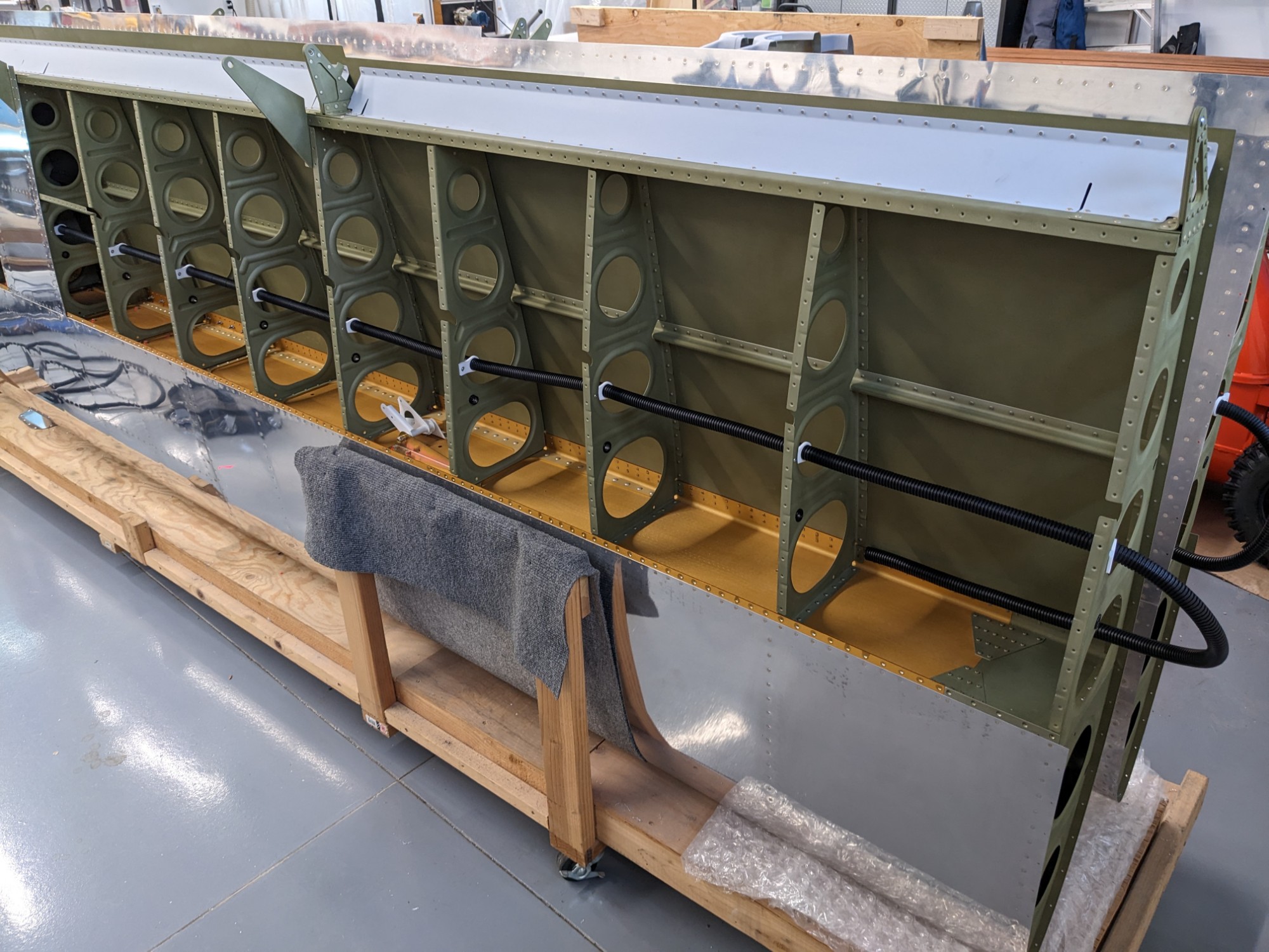
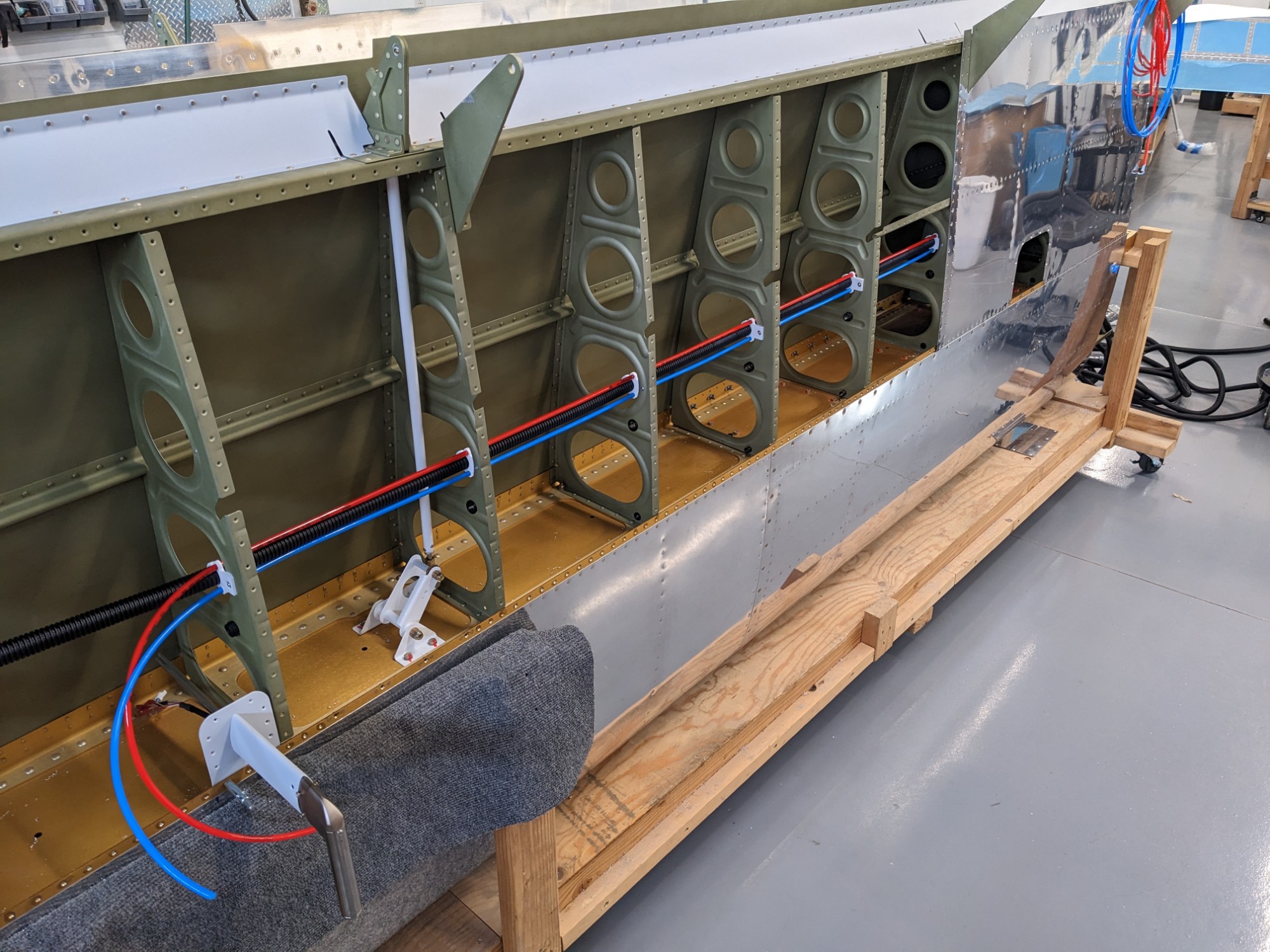
Before closing up the wings, I installed wiring conduit and secured the pitot and AoA lines.
The wiring conduit in the left wing will be used for wingtip lighting and power/sense for the regulated pitot tube. The wiring conduit in the right wing will be used for wingtip lighting, the autopilot roll servo, electric trim, and wiring to a Garmin GMU-11.
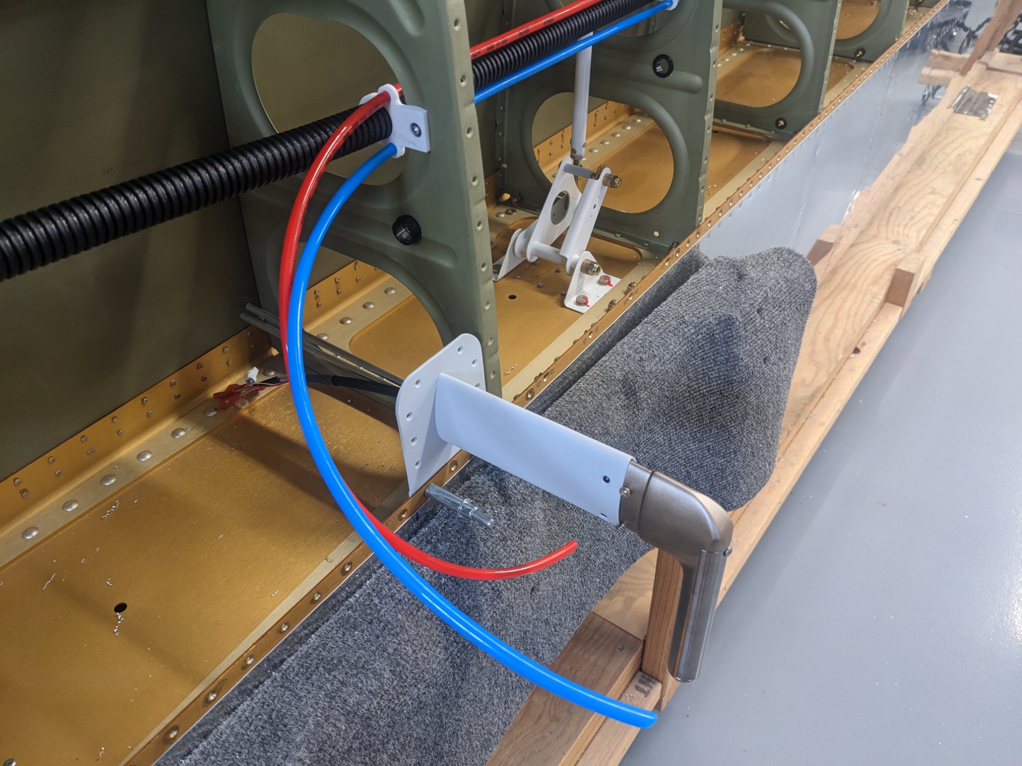
I initially planned on mounting Van’s conduit with SharkBite Suspension Clamps (as others have done), but that didn’t give me a clean way to secure the pitot and AoA lines.
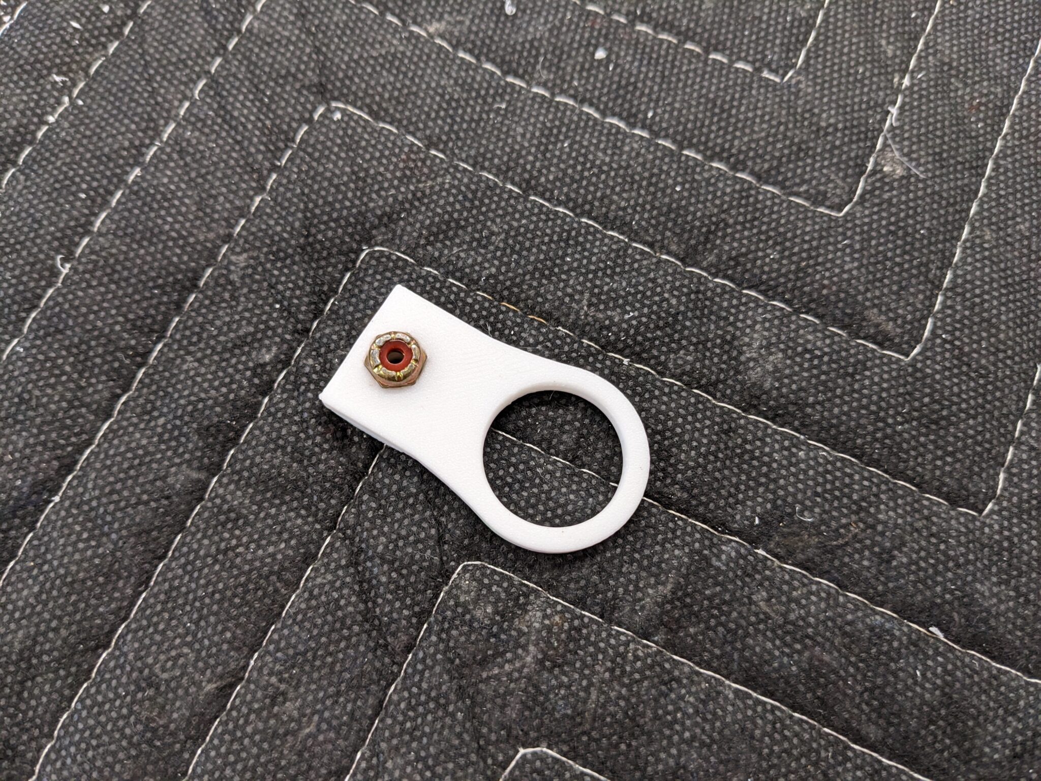
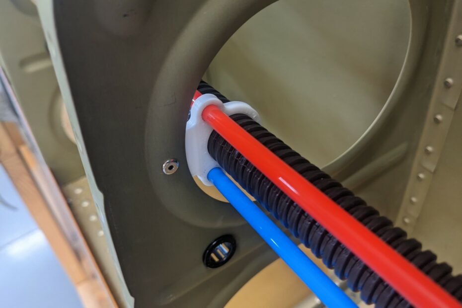
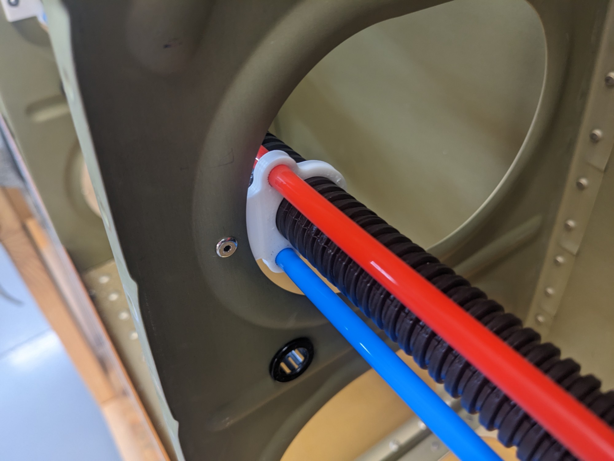
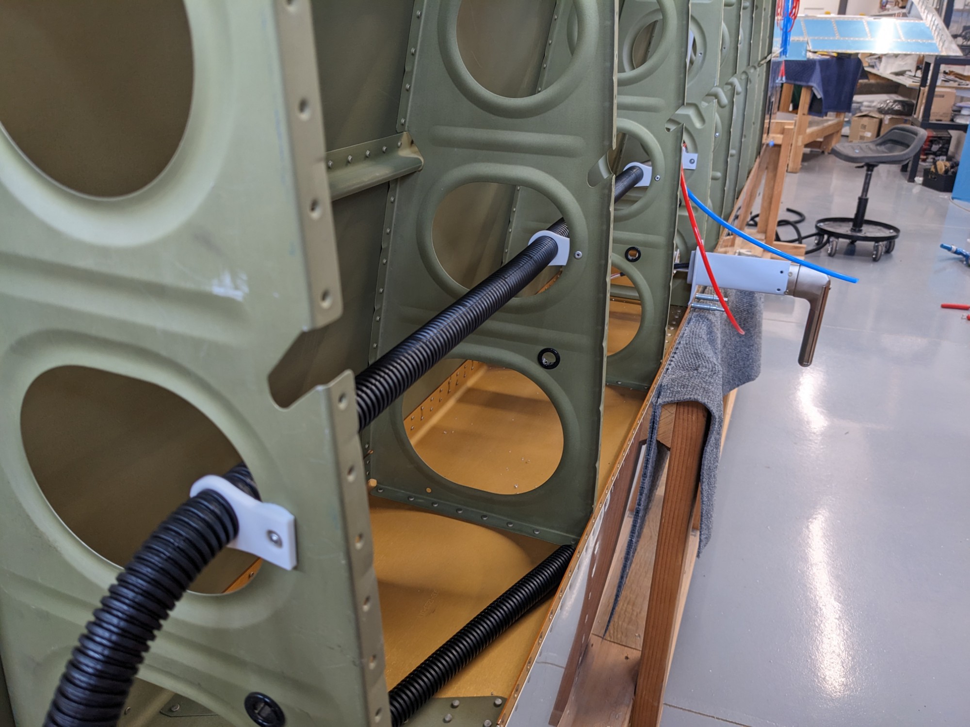
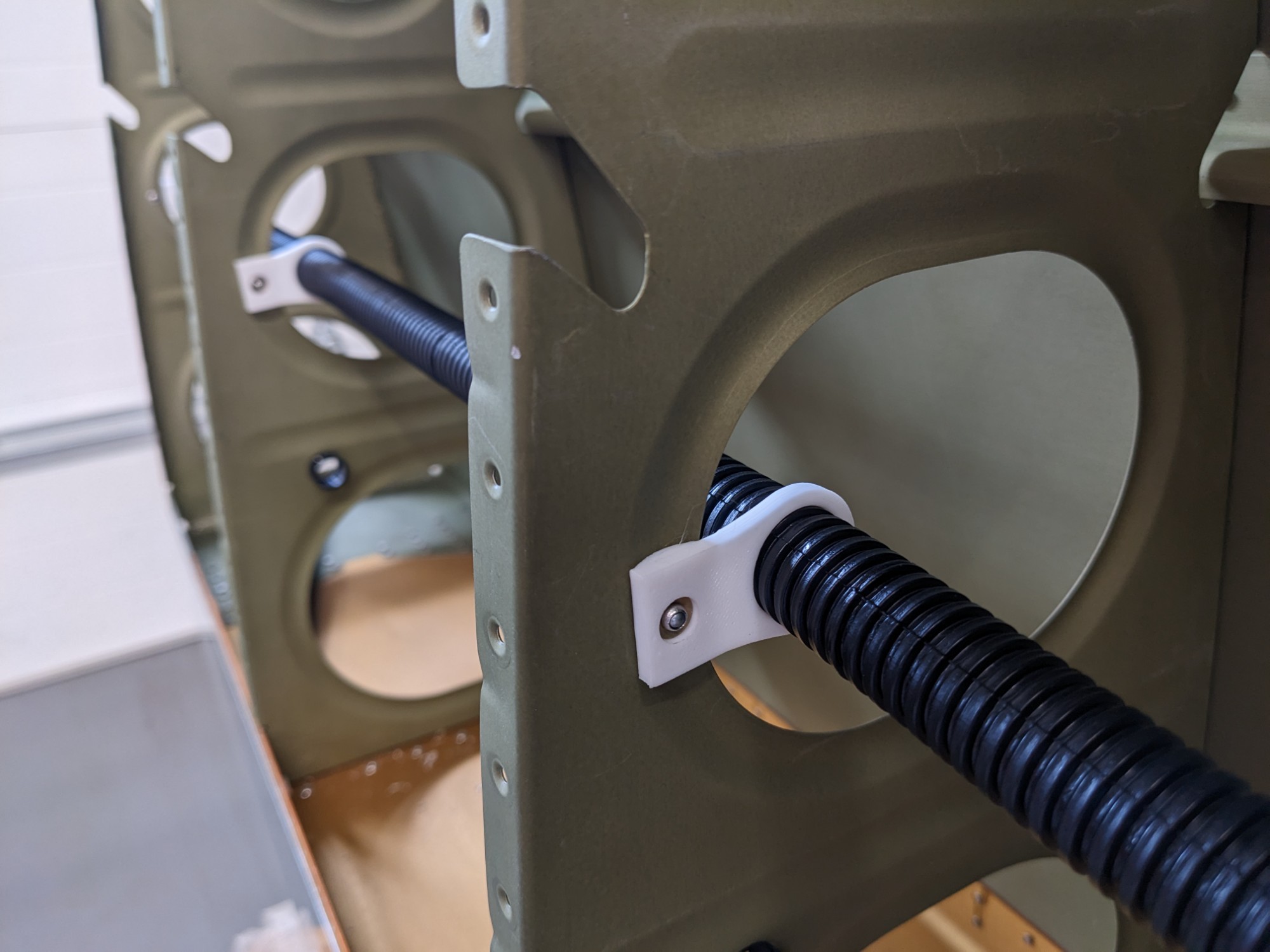
I ultimately decided to design some 3d printed brackets to secure the conduit and pitot/AoA lines. These were lighter than SharkBite clamps and only needed one blind rivet each (I matched the radius of the flange of the lightening holes to prevent rotation).
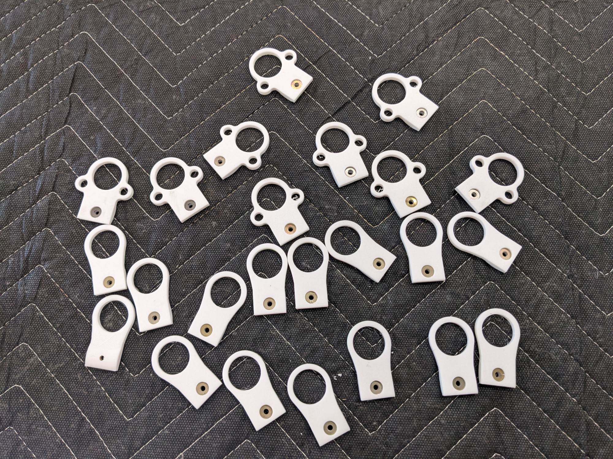
I printed them with polycarbonate (Polymaker PC Max), a very high temperature and strong material.
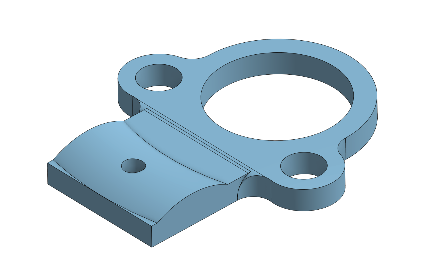
I pressed an AN960-4L washer inside each bracket for the blind side of the rivet to secure against.
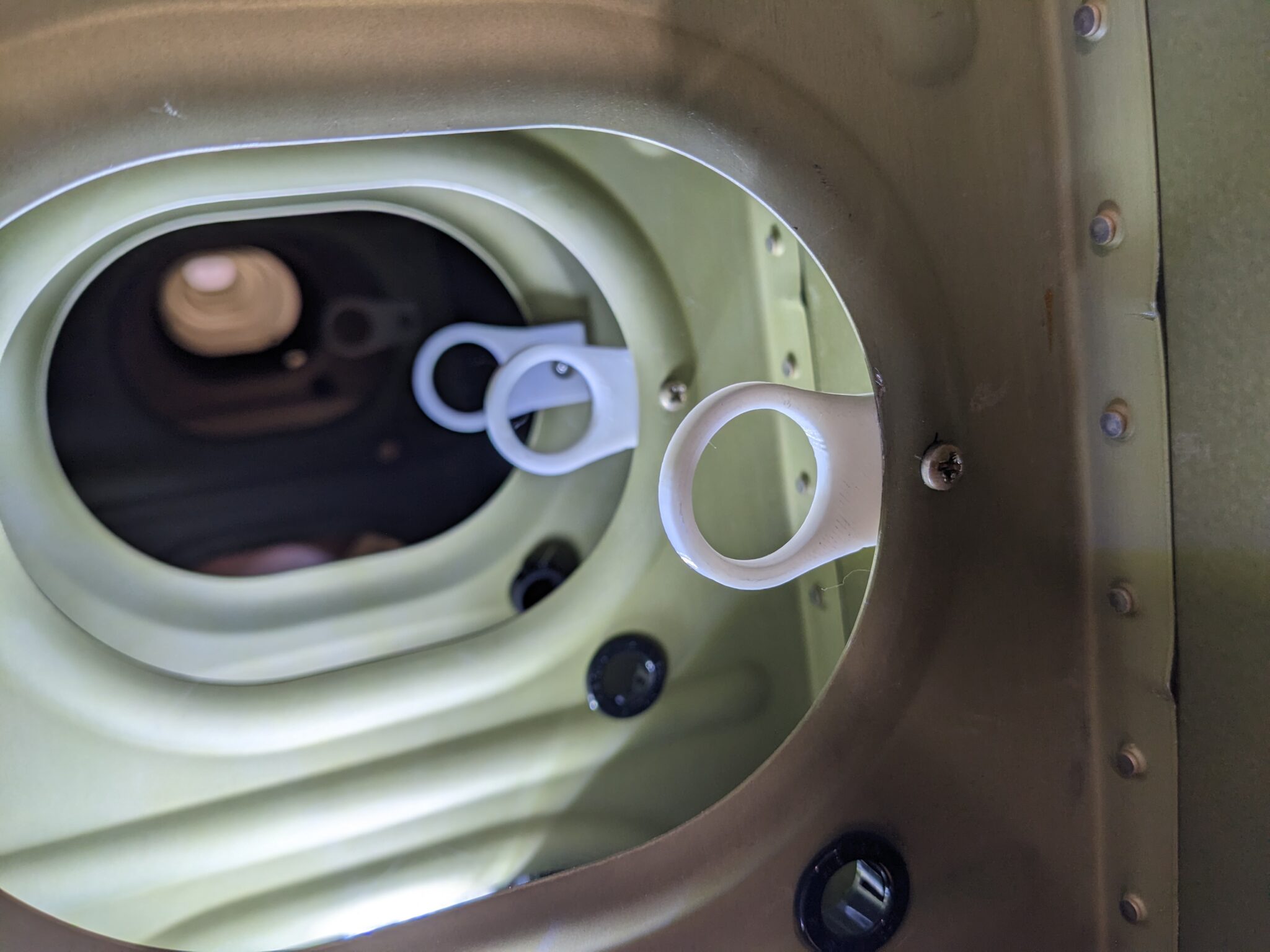
Before installing the brackets, I cleaned up the pitot/AoA holes with a 1/4″ drill bit and ran a deburring tool around all of the holes to radius them. It ended up being a bit challenging to feed the pitot/AoA lines through and, if I did it again, I might make those holes slightly larger. On the other hand, the lines aren’t going to move around as they are fairly snug in the holes.
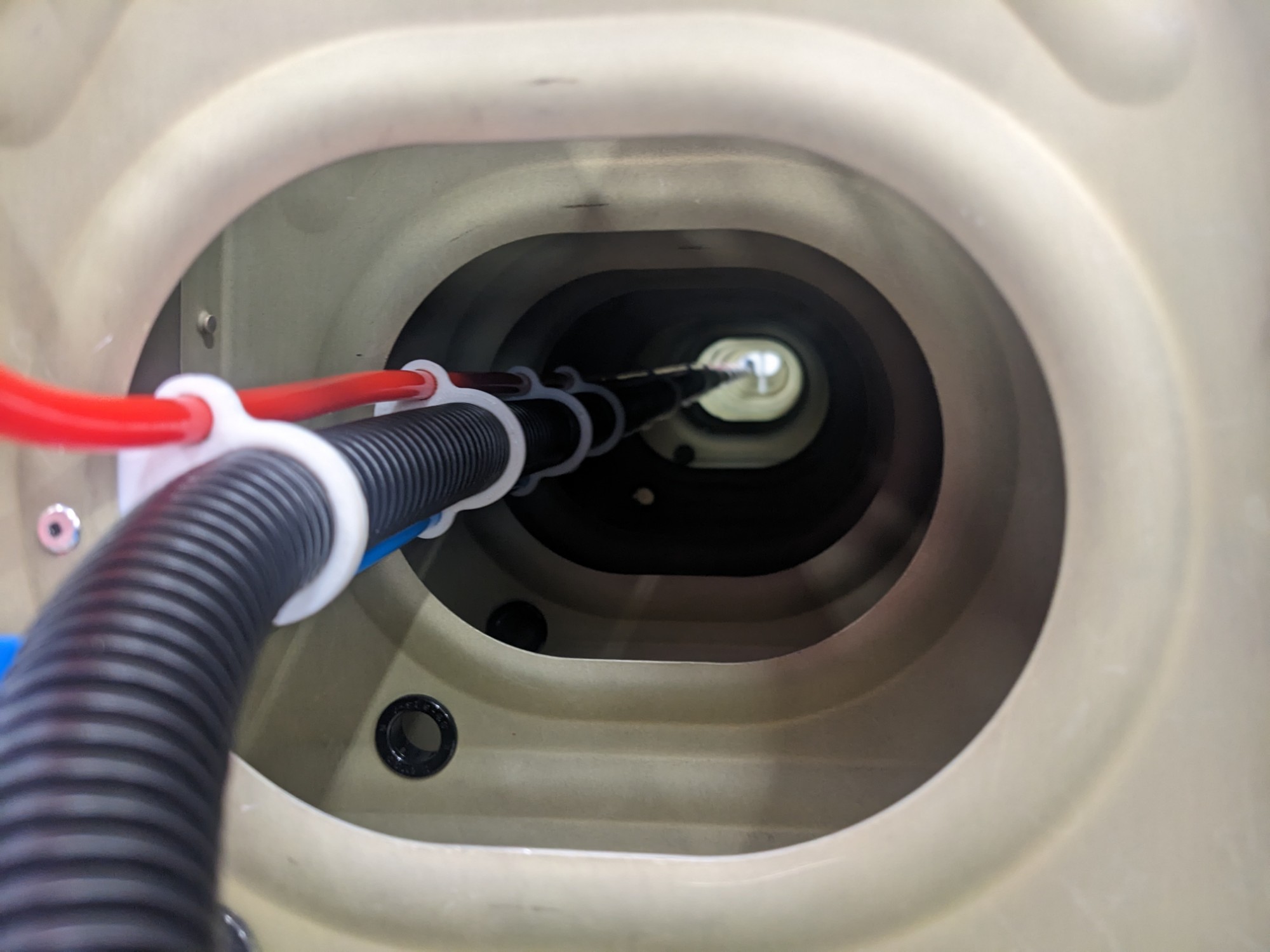
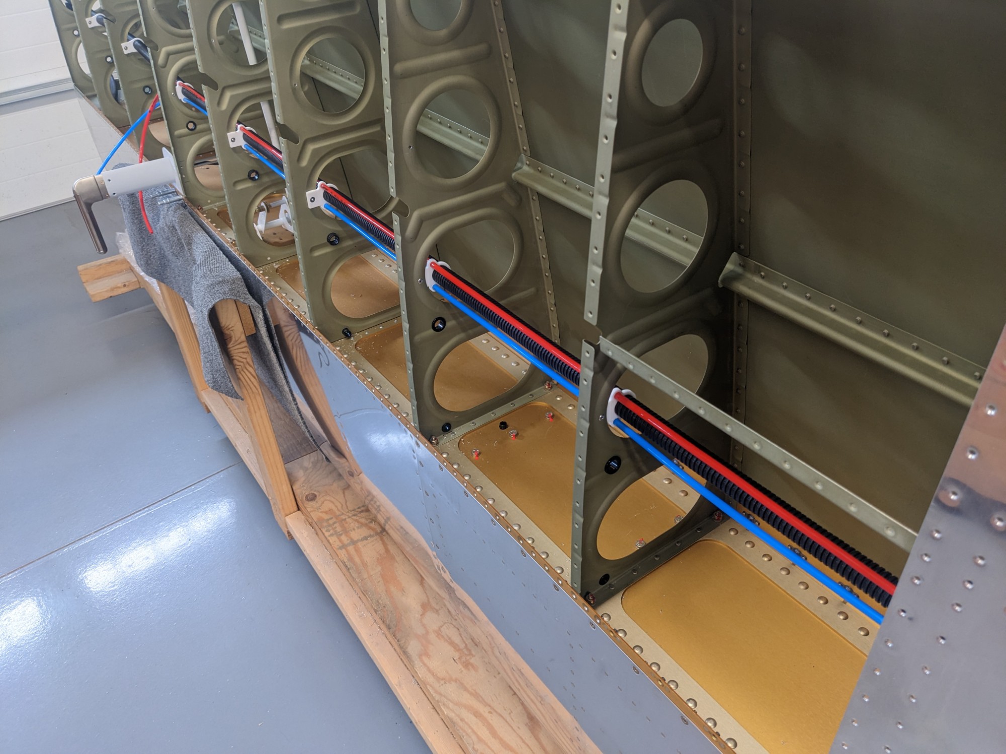
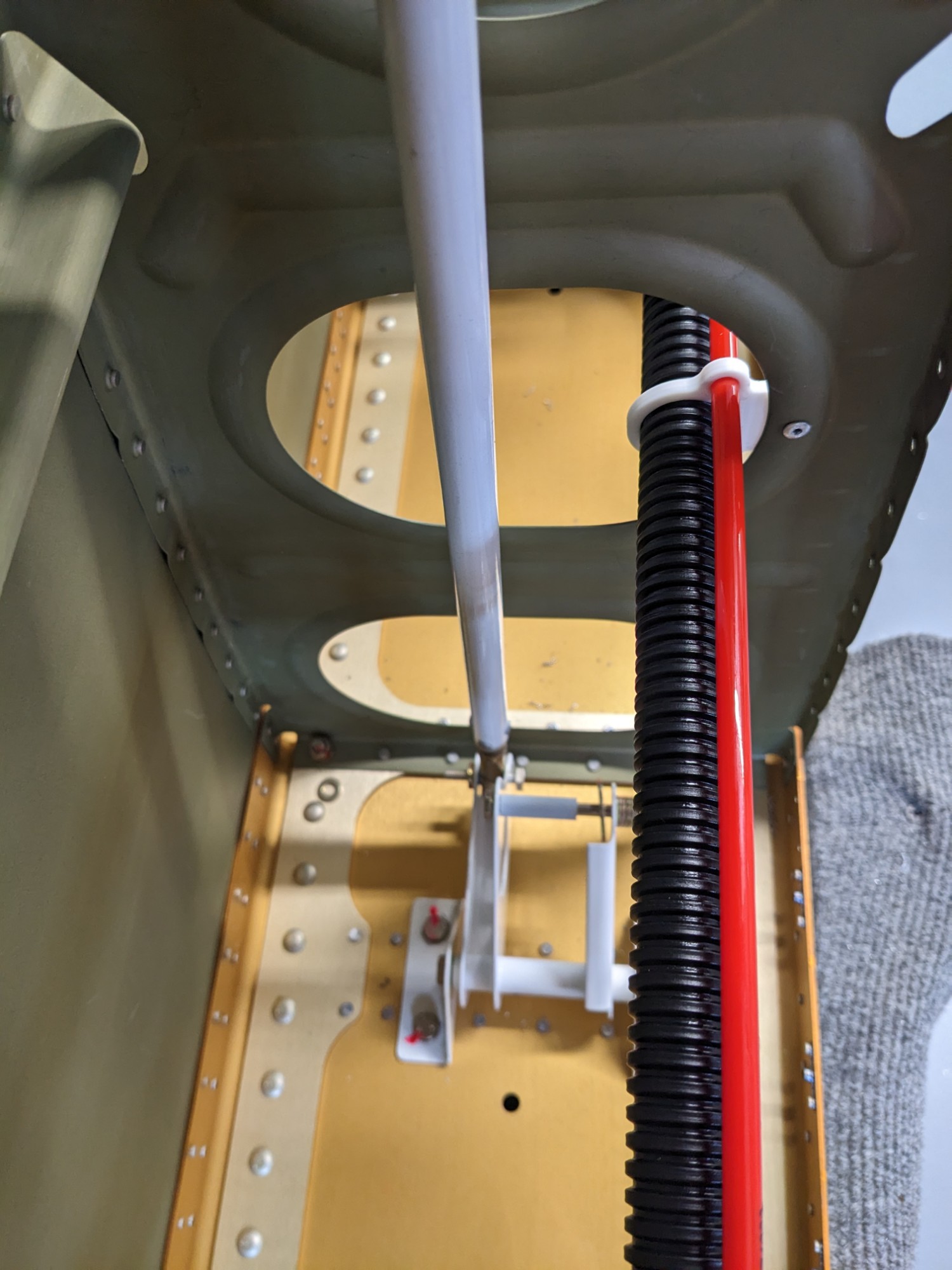
I used the 3-hole versions up to the pitot tube on the left wing and I installed 1-hole versions everywhere else.
I didn’t have enough room to pull a rivet for the two inner ribs in the wing walk area so I pressed an AN365-632A nut into these brackets and secured them with #6 screws.