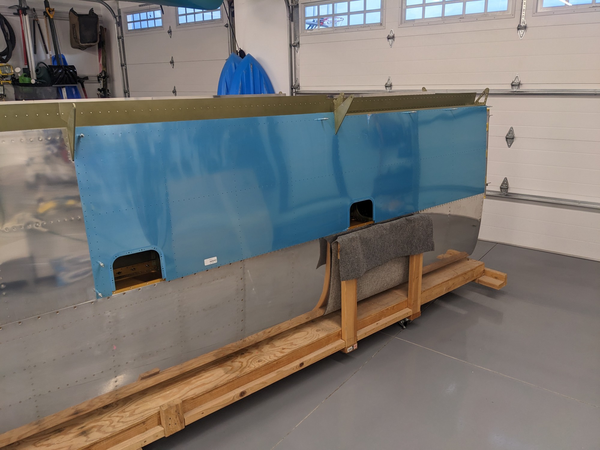
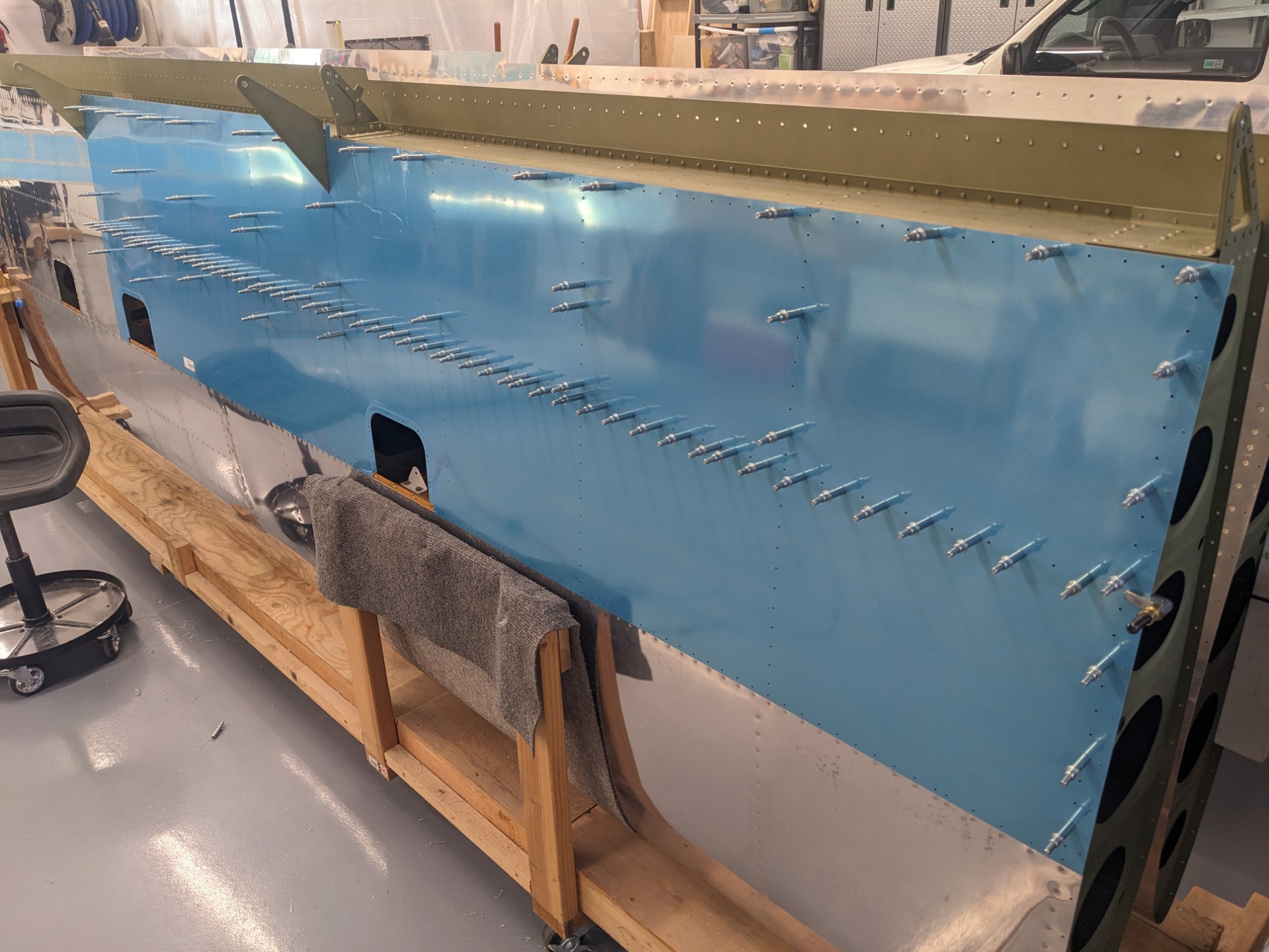
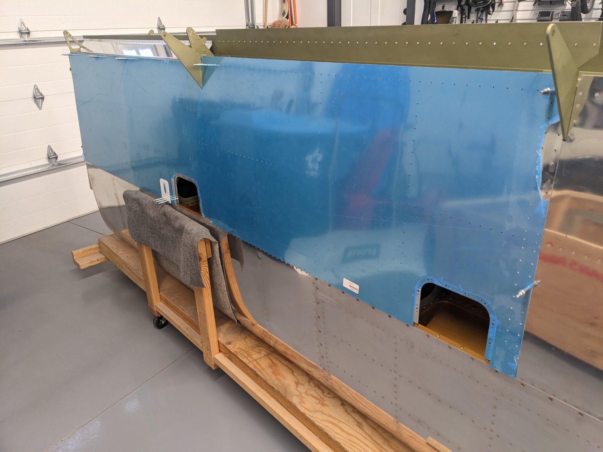
While waiting for some parts, I got the bottom wing skins ready. I also needed to determine where I would mount the Garmin GAP 26 Pitot/AoA.
This section starts with the aileron and flap gap fairings. These are the first (and only) parts I have received that use the new laser-cutting process.
My quick-build wings have punched holes so those parts must have been shipped out prior to the laser-cutting process being introduced.
The laser-cut holes are final-sized but are definitely not as clean as the punched holes. The start/stop position in each hole is visible so I ran a reamer through many of them to clean them up before deburring and dimpling. Thankfully these are the only laser-cut parts I have received as they took more effort to deburr.

I then cut the j-stiffeners to length. The longer stiffener overlaps on the outside of the shorter stiffeners per the earlier instructions in the normal build plans.
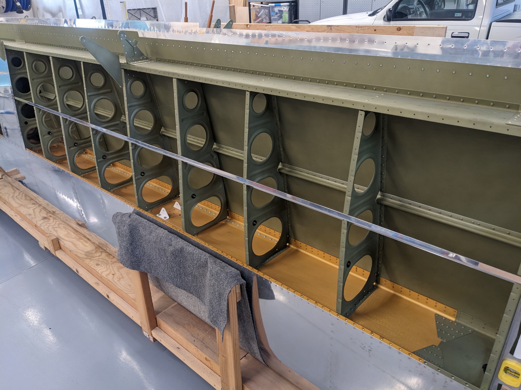
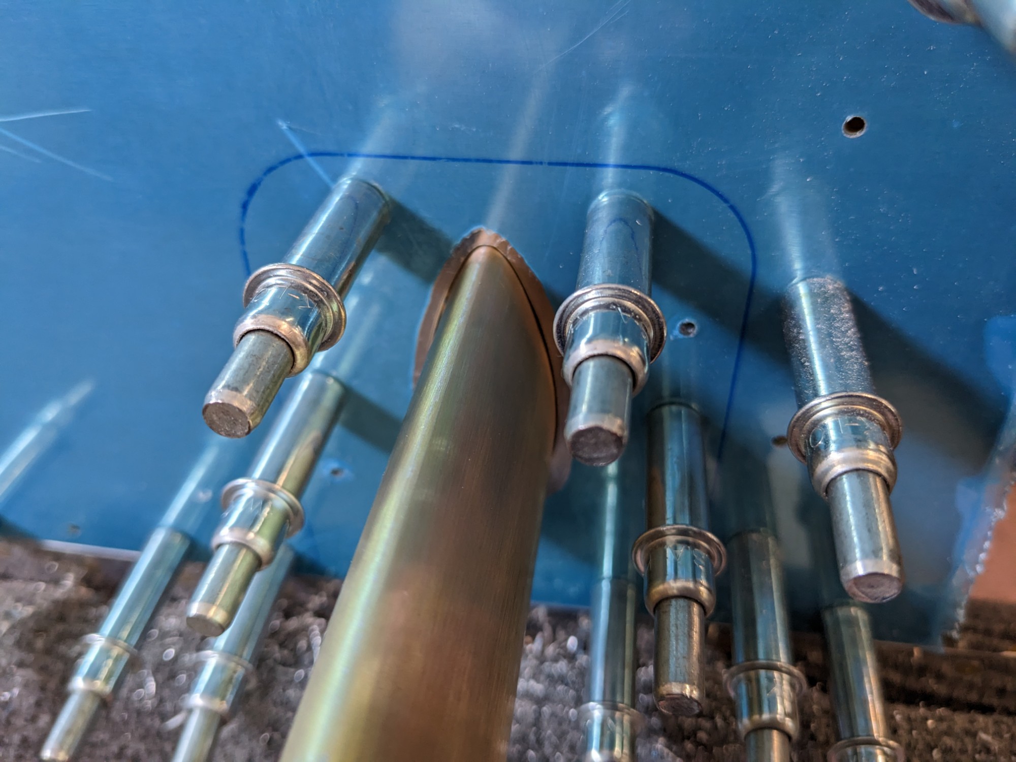
I then clecoed the bottom skins into place and match-drilled the j-stiffeners.
Pitot Tube
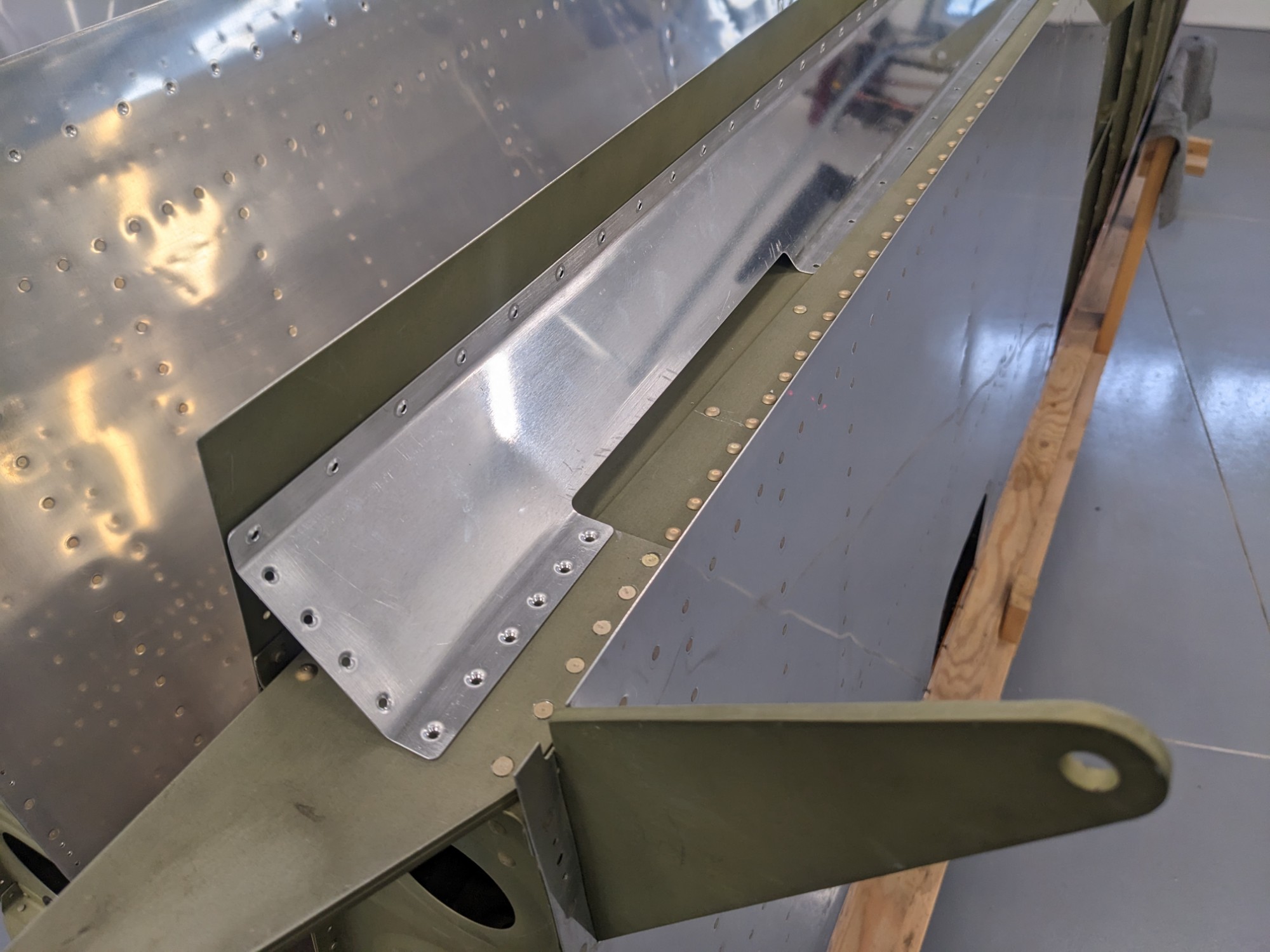
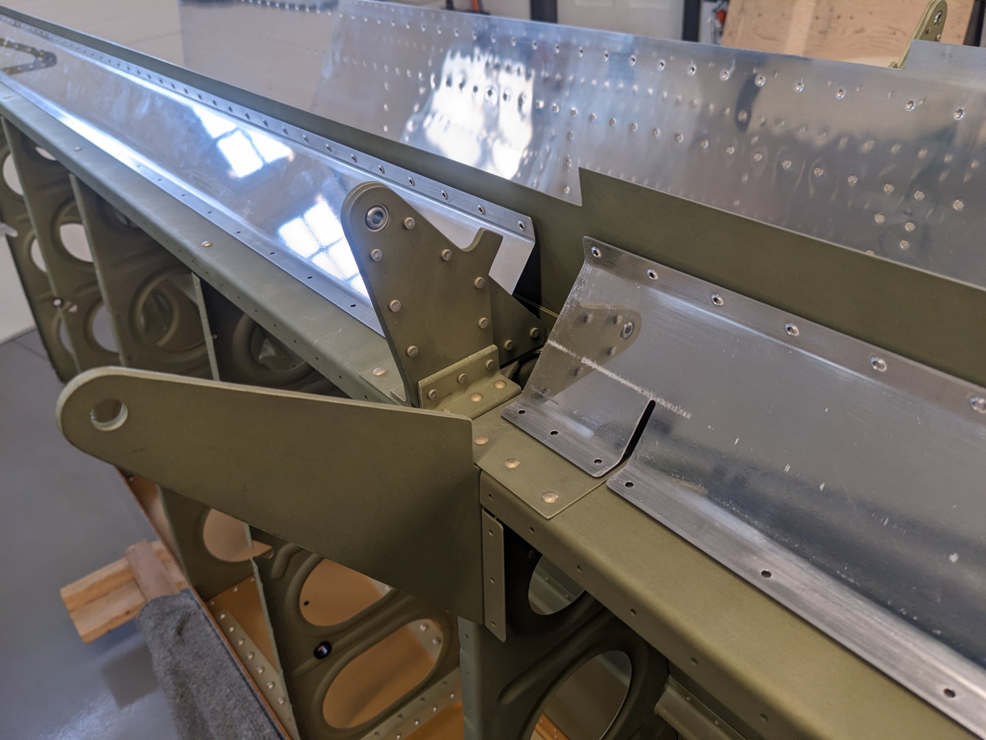
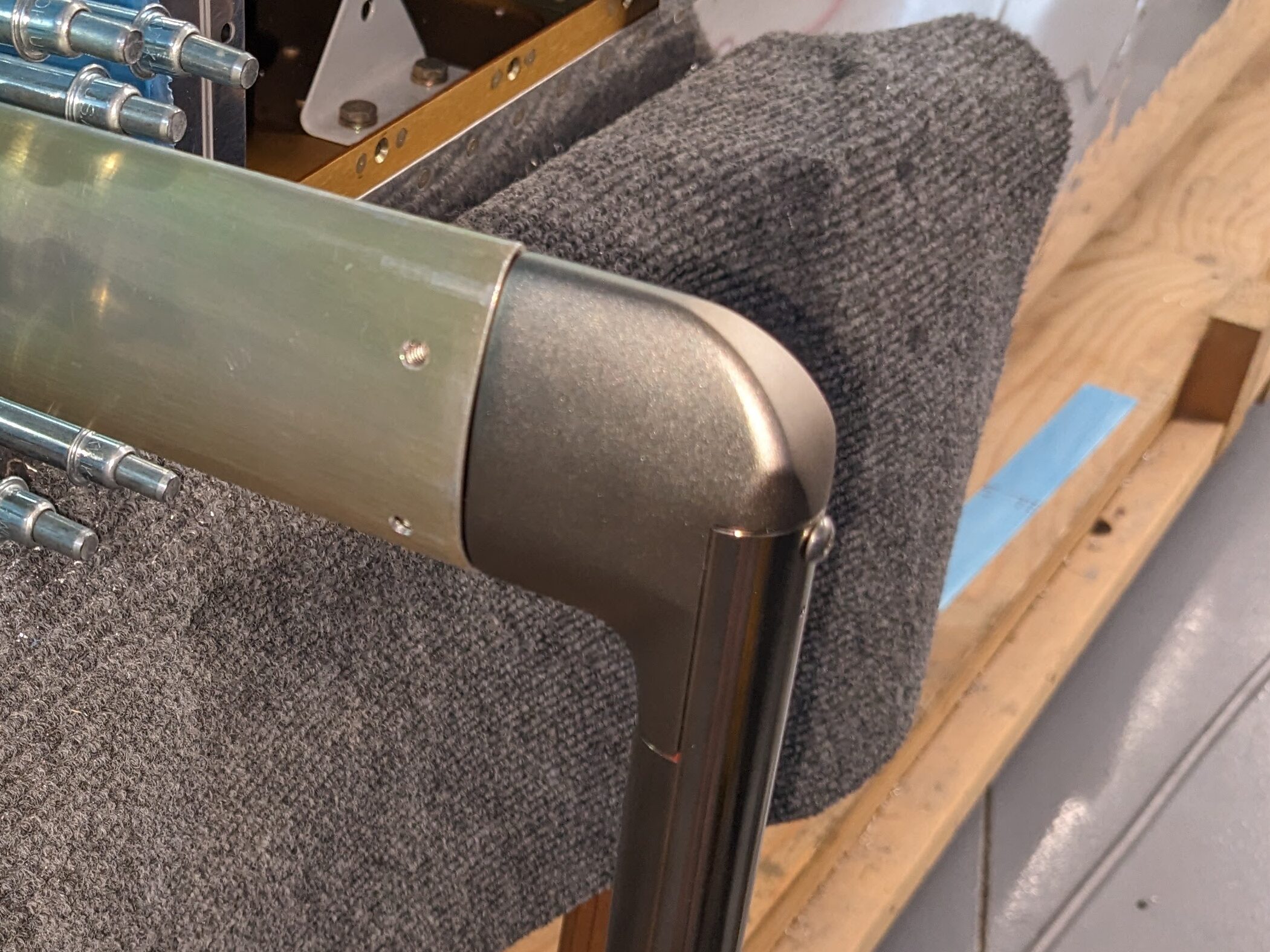
I chose the Dynon Pitot Mount Bracket as it is reasonably priced and looks to be well made. The mount is specifically made for RVs and the mounting plate matches the curve of the bottom wing skin. The aft part of the bracket is riveted to the wing spar flange.
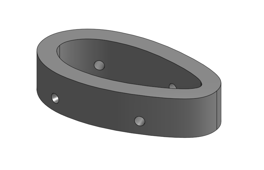
The mount uses the standard AN5812 profile which is used by the Garmin GAP 26. The screw holes to attach the pitot tube are not predrilled. I wanted to make a 3D-printed template for cutting the hole in the wing so I looked up the AN5812 spec and drafted up the profile in Onshape.
I used this profile to make a drill guide for match-drilling the holes in the pitot mount.
Part: Dynon Mount Drill Guide
The holes aligned perfectly and had the correct angle (yay for specs, even when hand-drafted in the 50’s and barely readable).
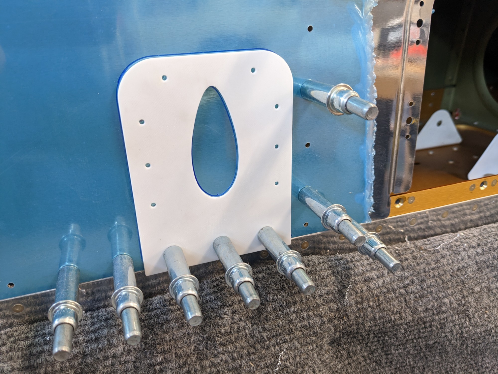
I have chosen to mount the pitot tube on the left wing (as per the plans) but one bay outboard from the aileron bell crank. This location has been used by other builders as it keeps the pitot tube clear of the aileron bell crank and clear of the wing tie-down. I used the AN5812 profile to create a template for aligning the mount with the spar.
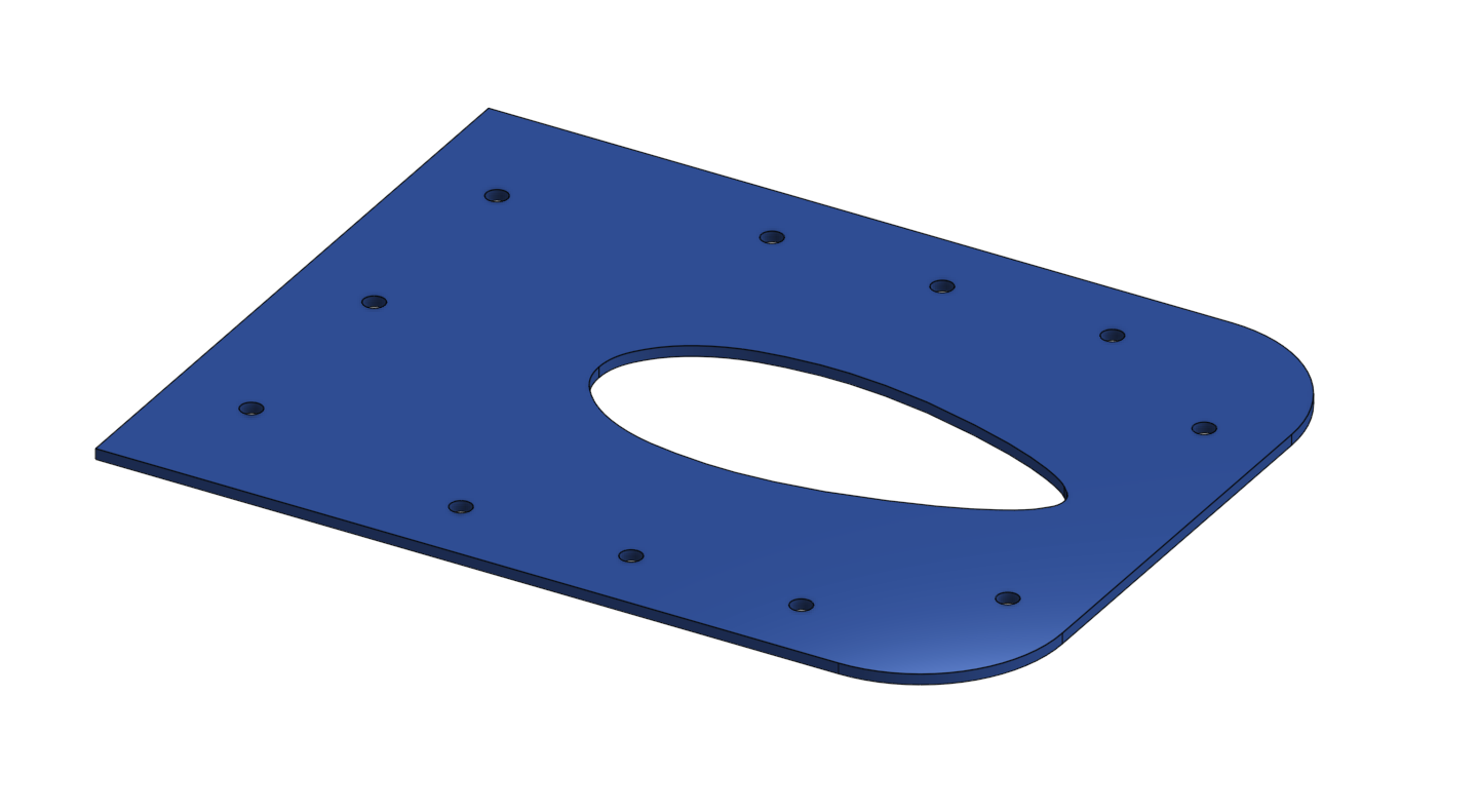
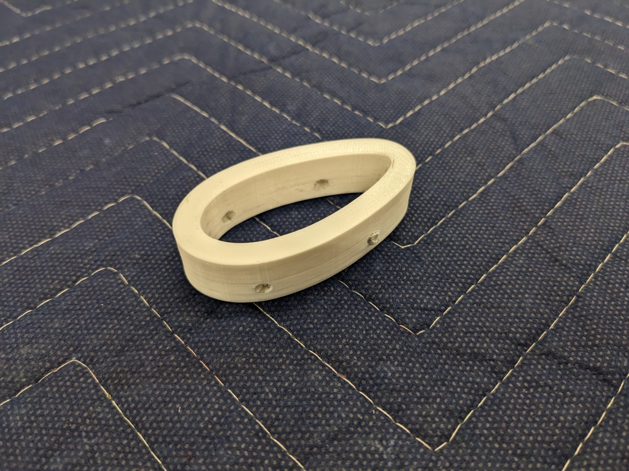
Part: Pitot Mount Template
The template slips over the mount and will allow me to match-drill the holes through the skin and into the mount. The holes along the flange match the spacing of the holes in the spar flange and can be clecoed into place for match drilling. I had to trim the flange on the Dynon pitot mount about 1/8″ to clear the shop heads that attach the forward bottom wing skin.
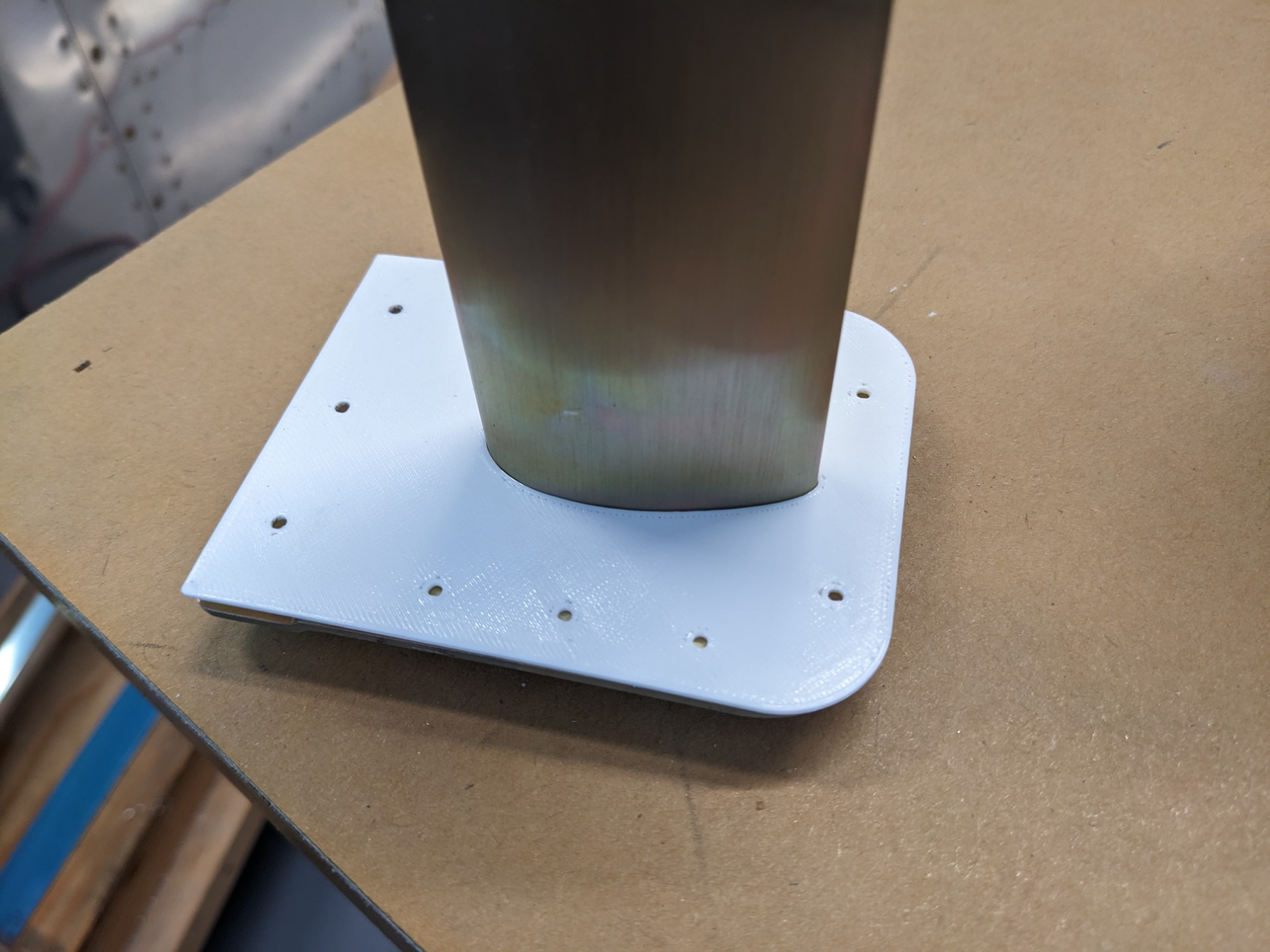
I clecoed the template to the skin, then marked the opening for the mount.
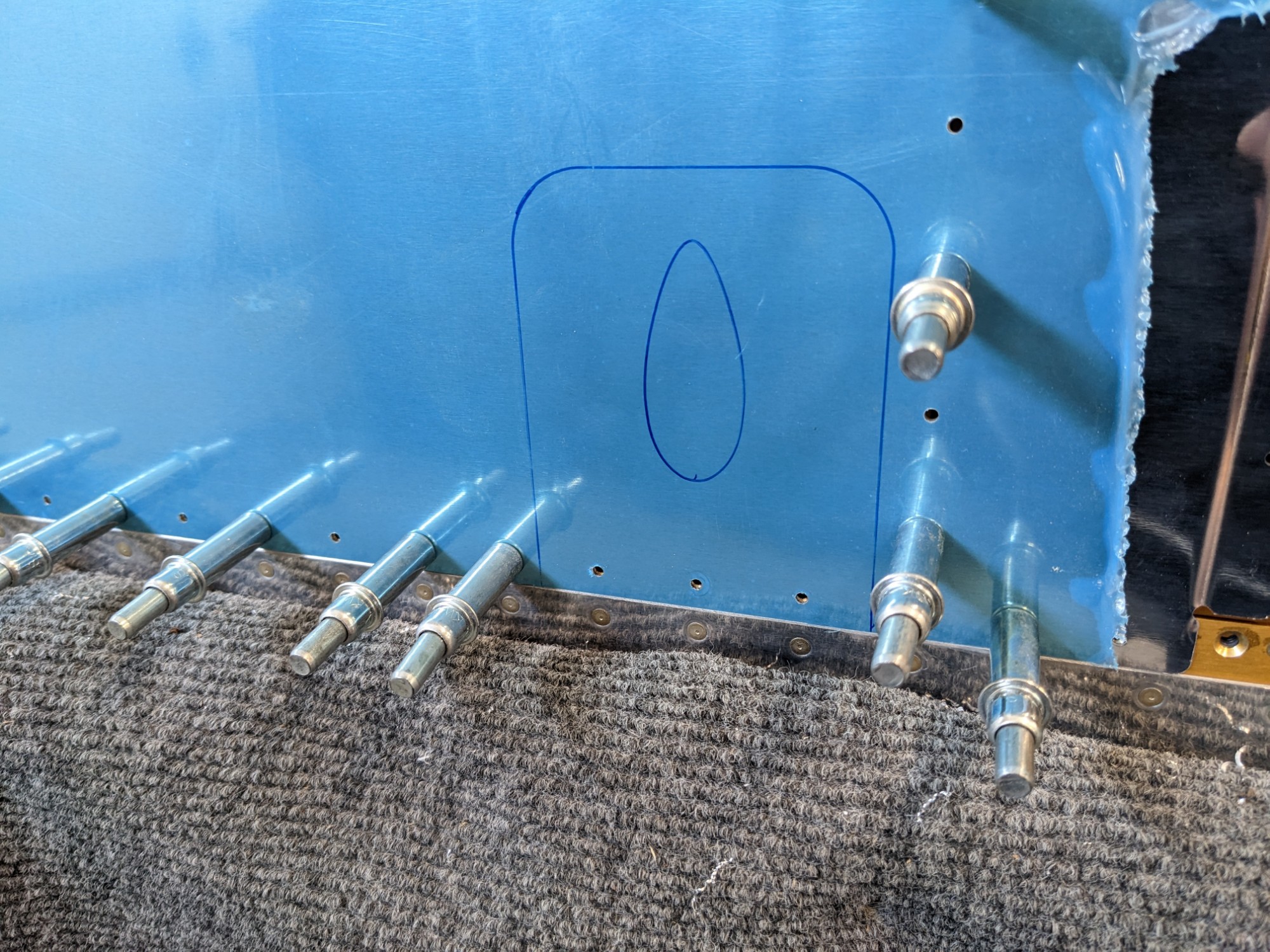
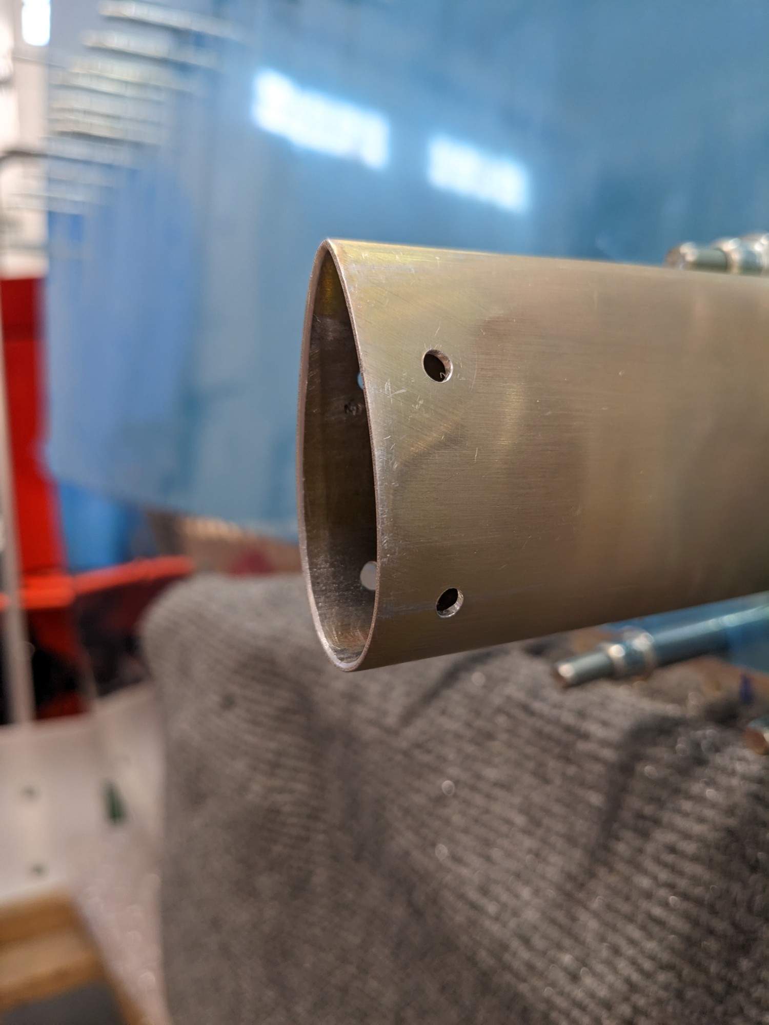
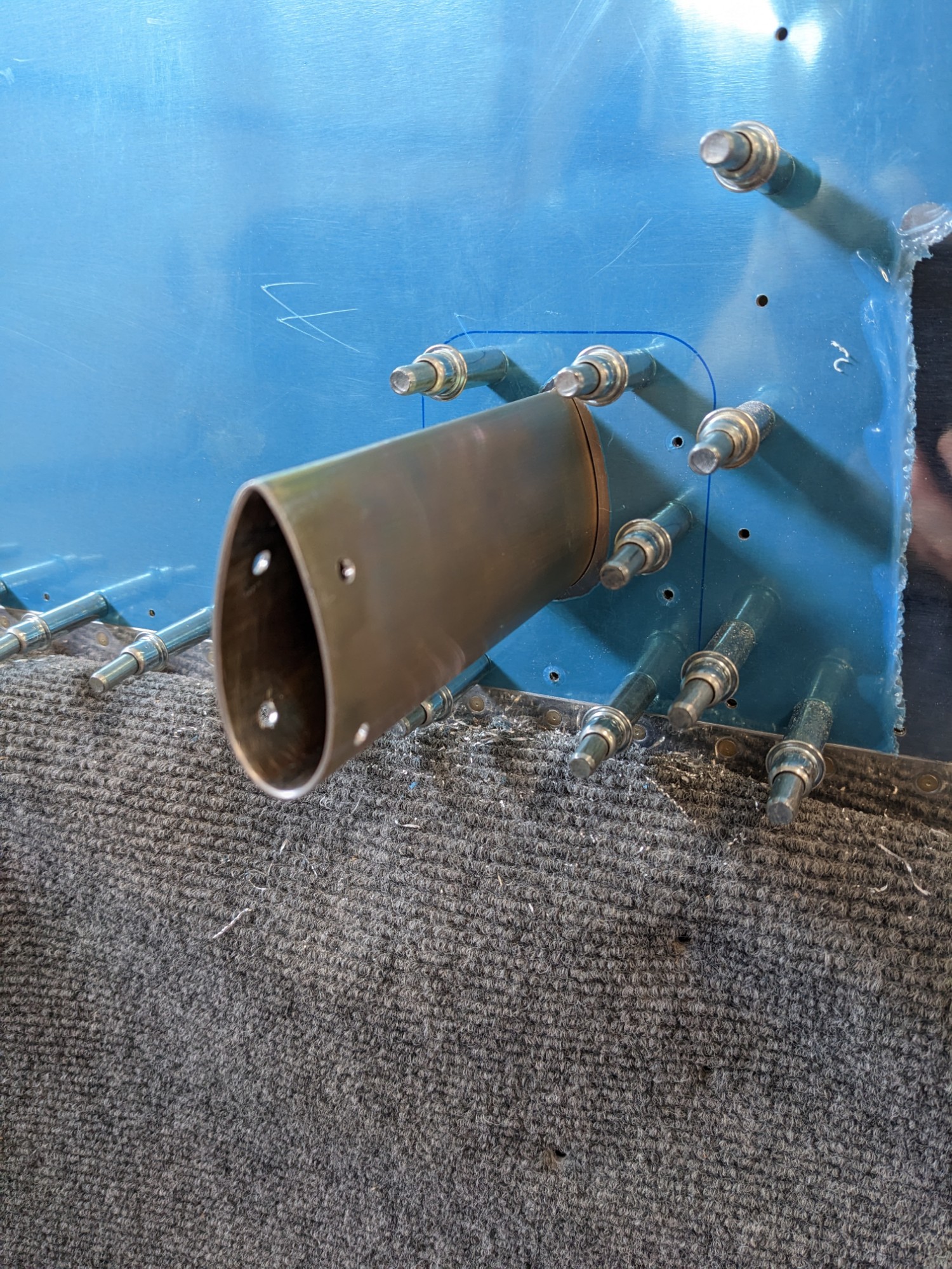
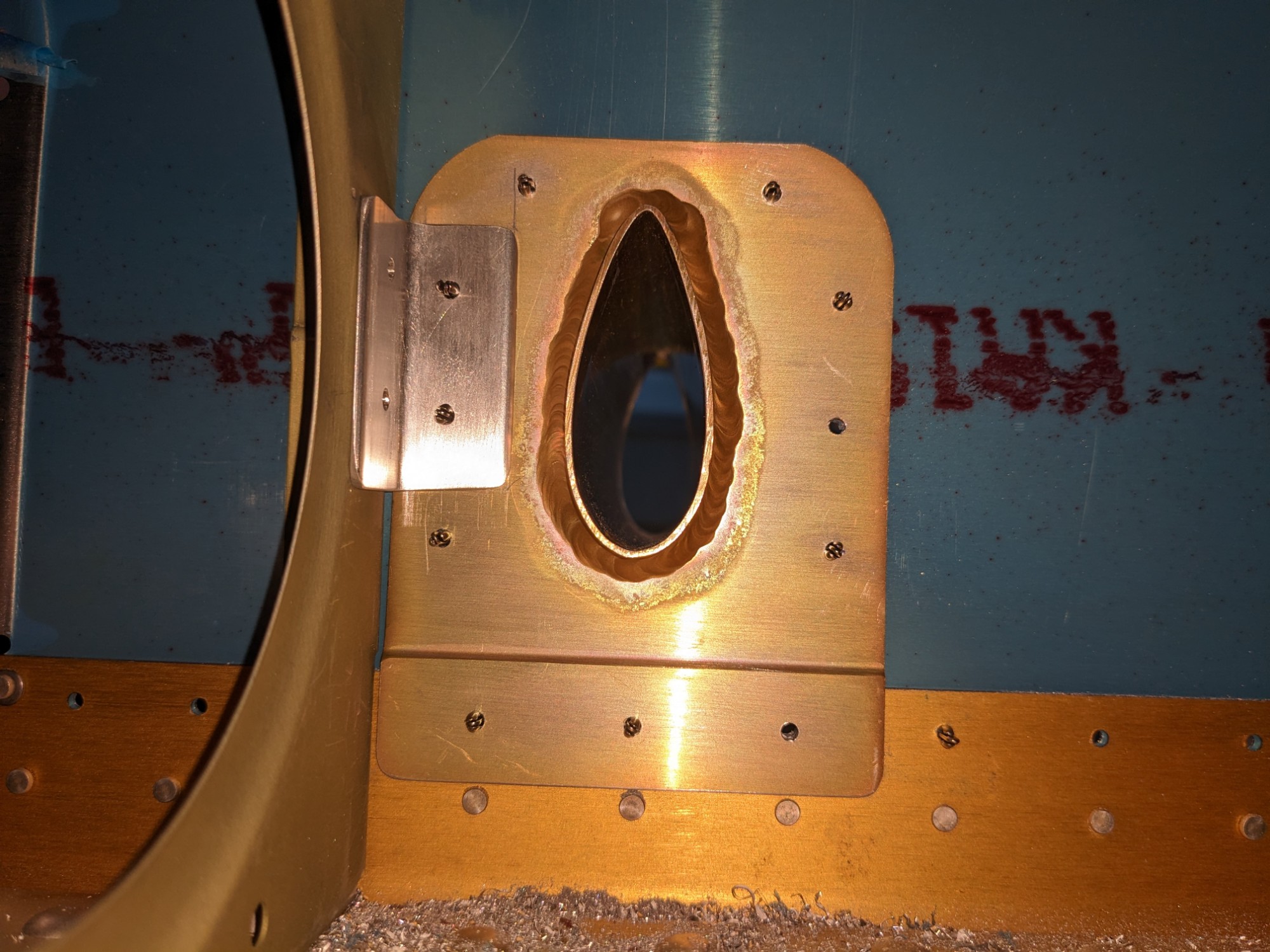
I used a step drill to rough cut the hole. I then finished it with a Dremel and some files. After inserting the pitot mount from the inside, I used the template to match drill the remaining holes.
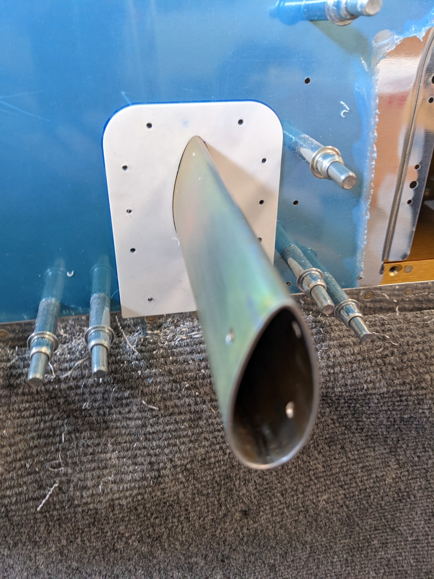
The final hole came out really clean and everything is well aligned.
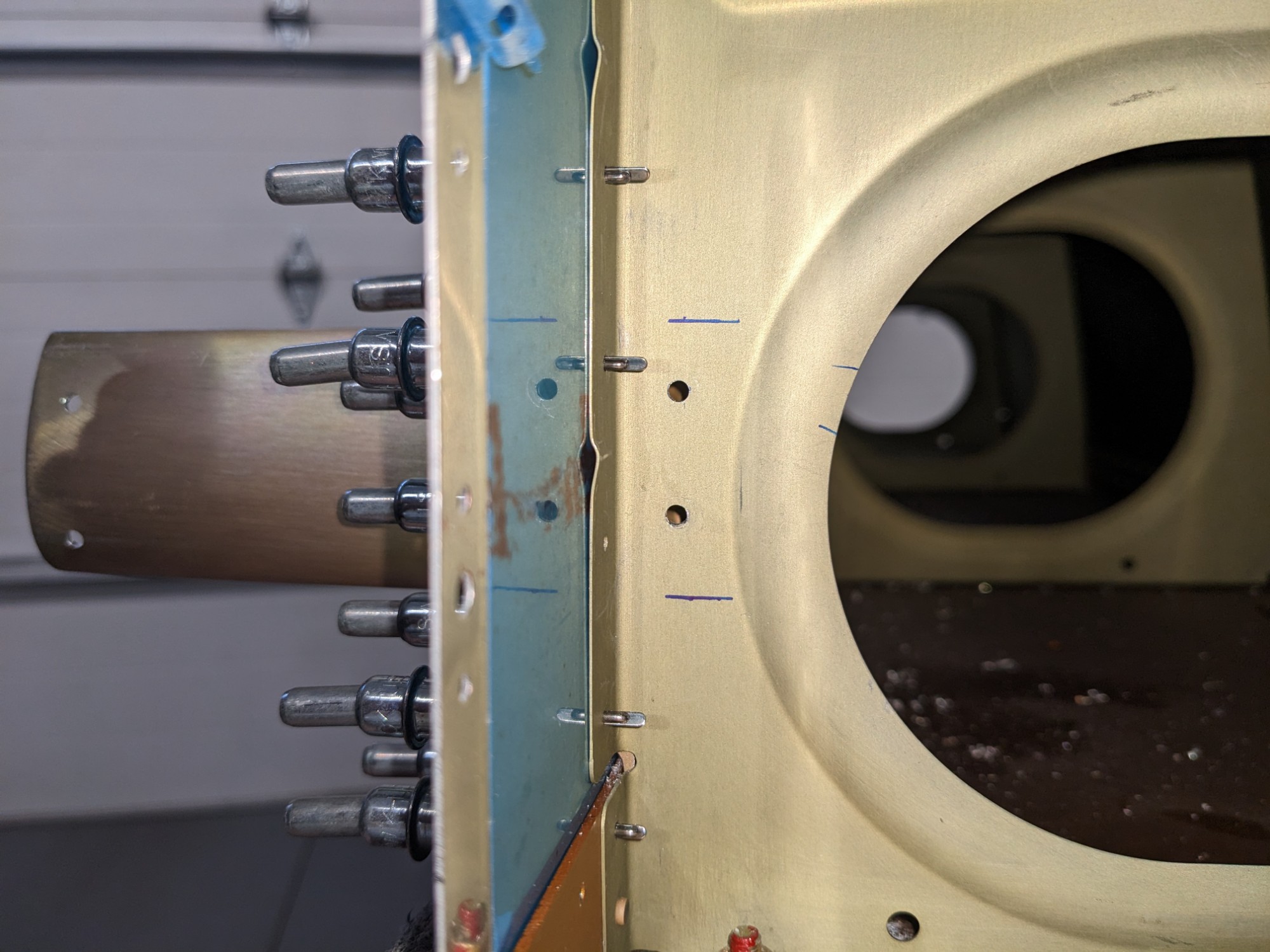
I then fabricated a bracket to attach the mount to the rib that sits beside it. This creates a bit more rigidity and should reduce skin flexing near the rib. I chose not to use the angle that came with the mount as I felt like it was too short (it would have only caught one of the rivets in the pitot mount).
I used a piece of .063″ angle which I match-drilled through the mount. I then drilled #30 holes through the wing rib web into the angle.
For the final install, I’ll first rivet the bottom skin into place, then insert the mount and rivet into place.
I ordered MS24693S24 screws and I’ll countersink the holes in the pitot mount before installing it.