I wasn’t thinking much about wiring needs when I assembled the vertical stabilizer at the beginning of the project. With the nav antenna mounted at the top, I needed some way to route the coax.
I also am considering power for a camera so I wanted to get a conduit run up into the tip fairing area.
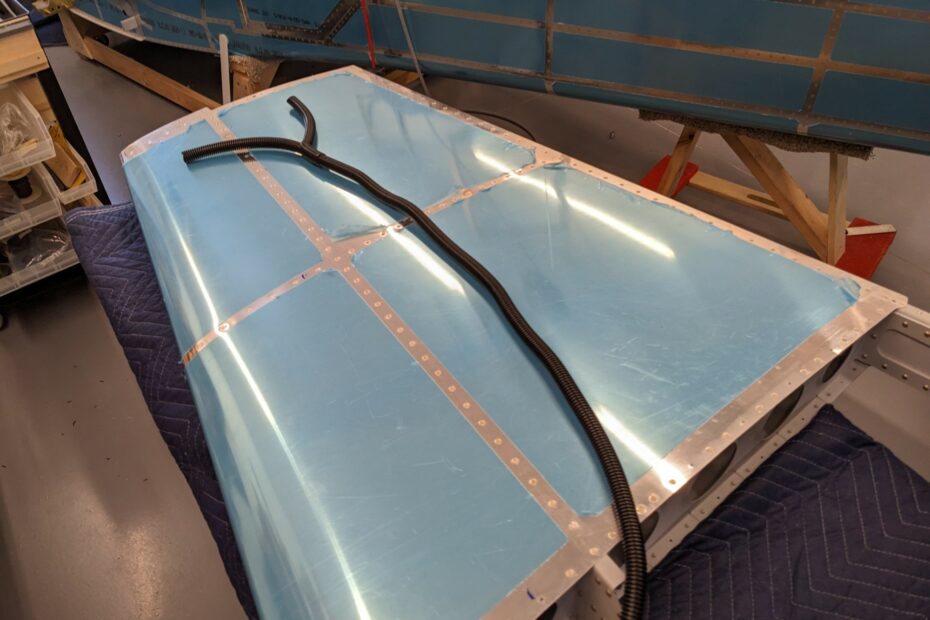
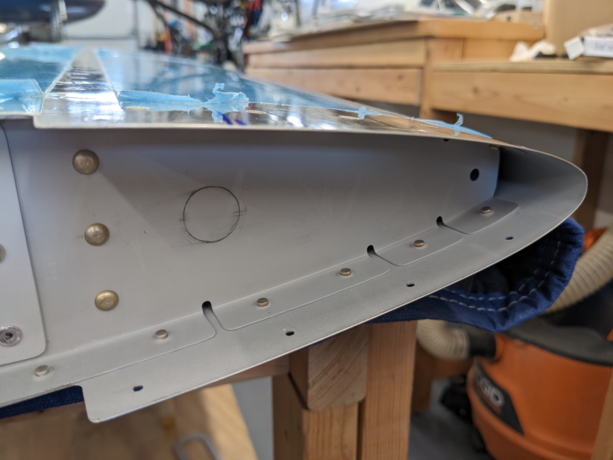
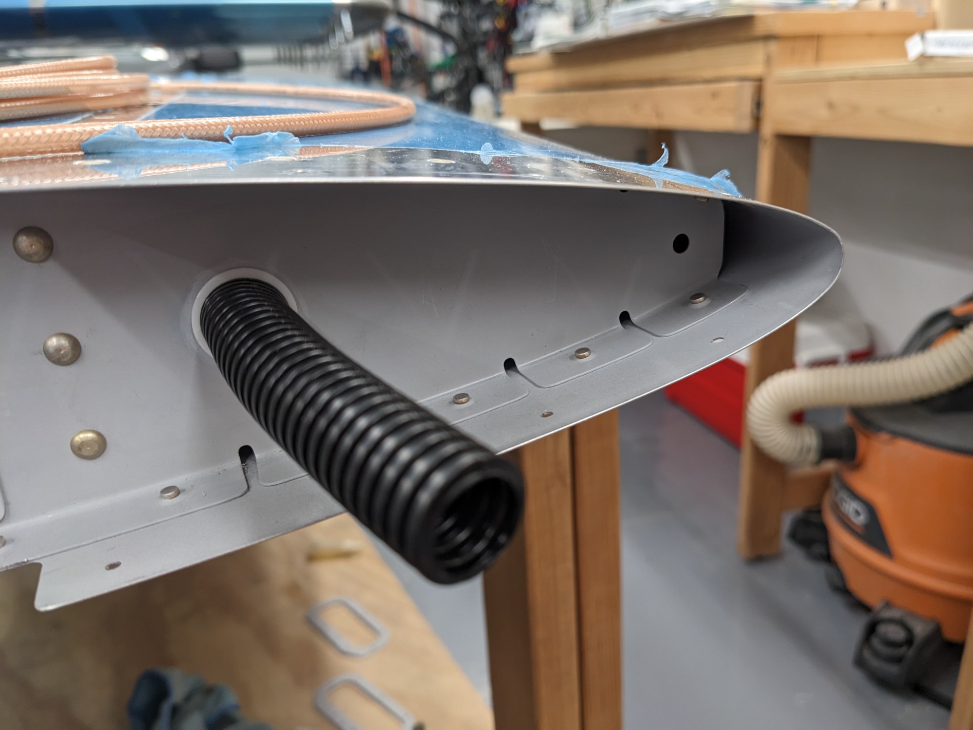
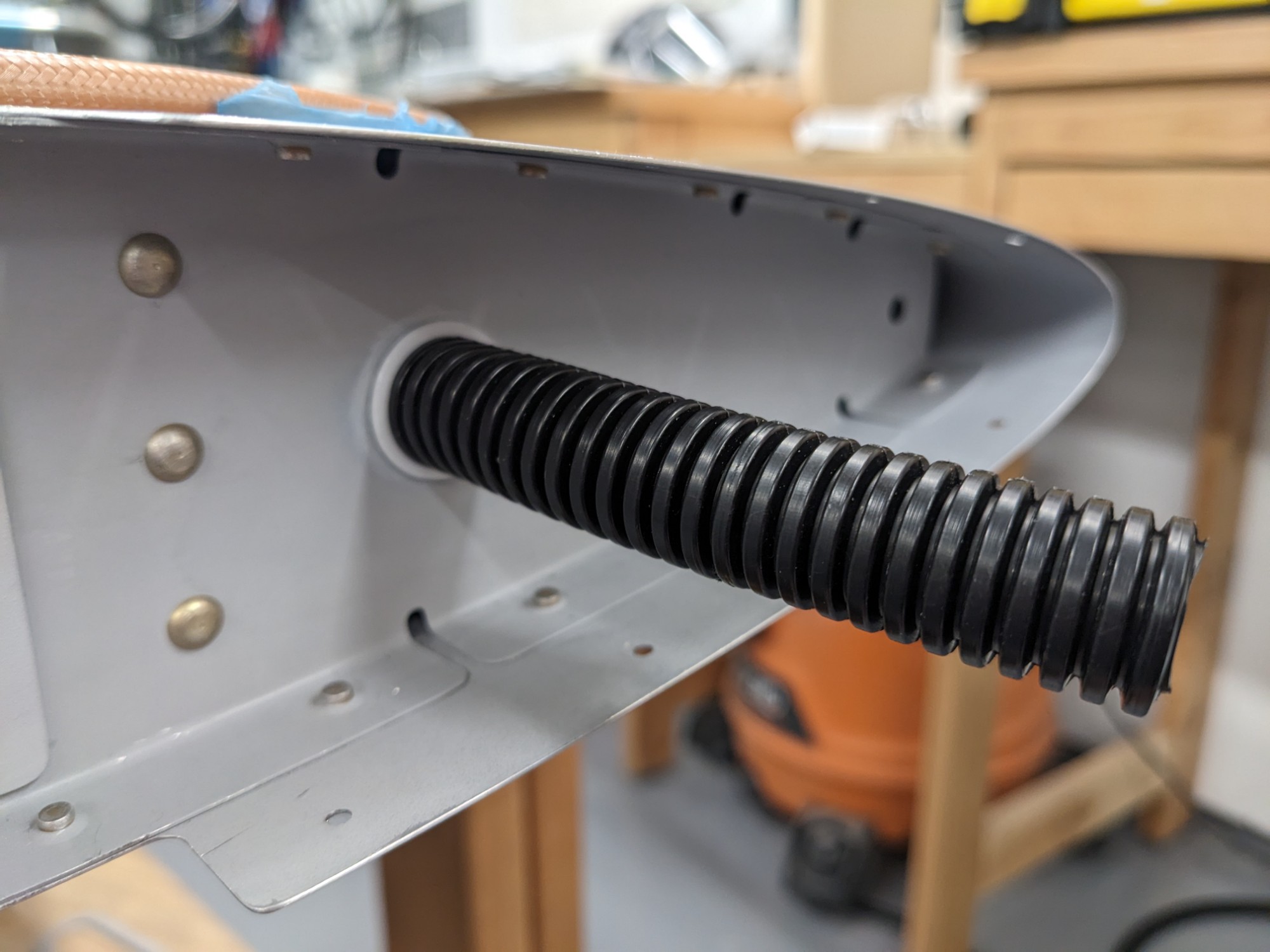
I started by drilling a hole under the tip fairing for 1/2″ conduit.
I then added a branch to the conduit to branch off to the nav antenna hole. I secured the branch with some grip lock ties and self-fusing tape.
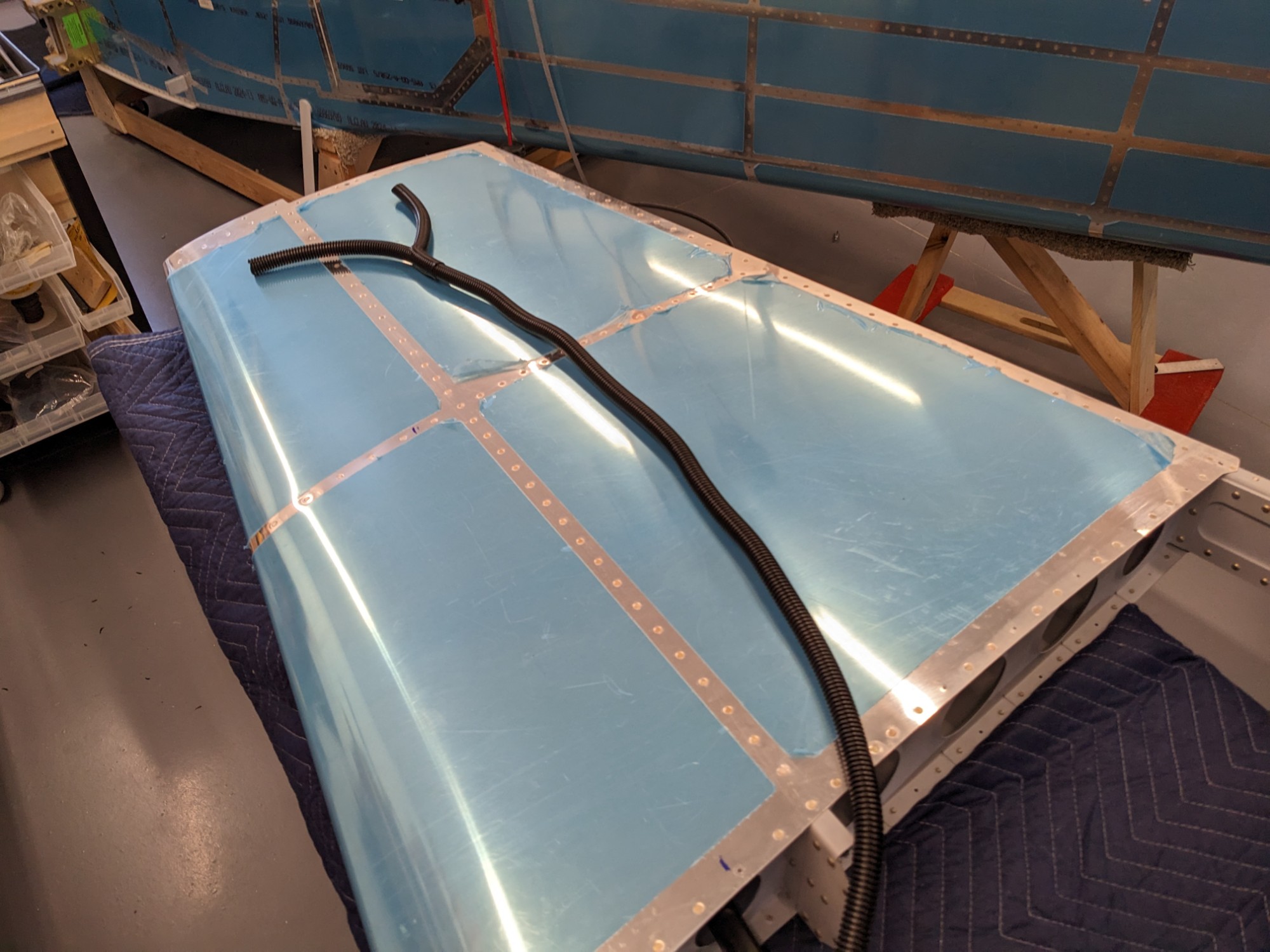
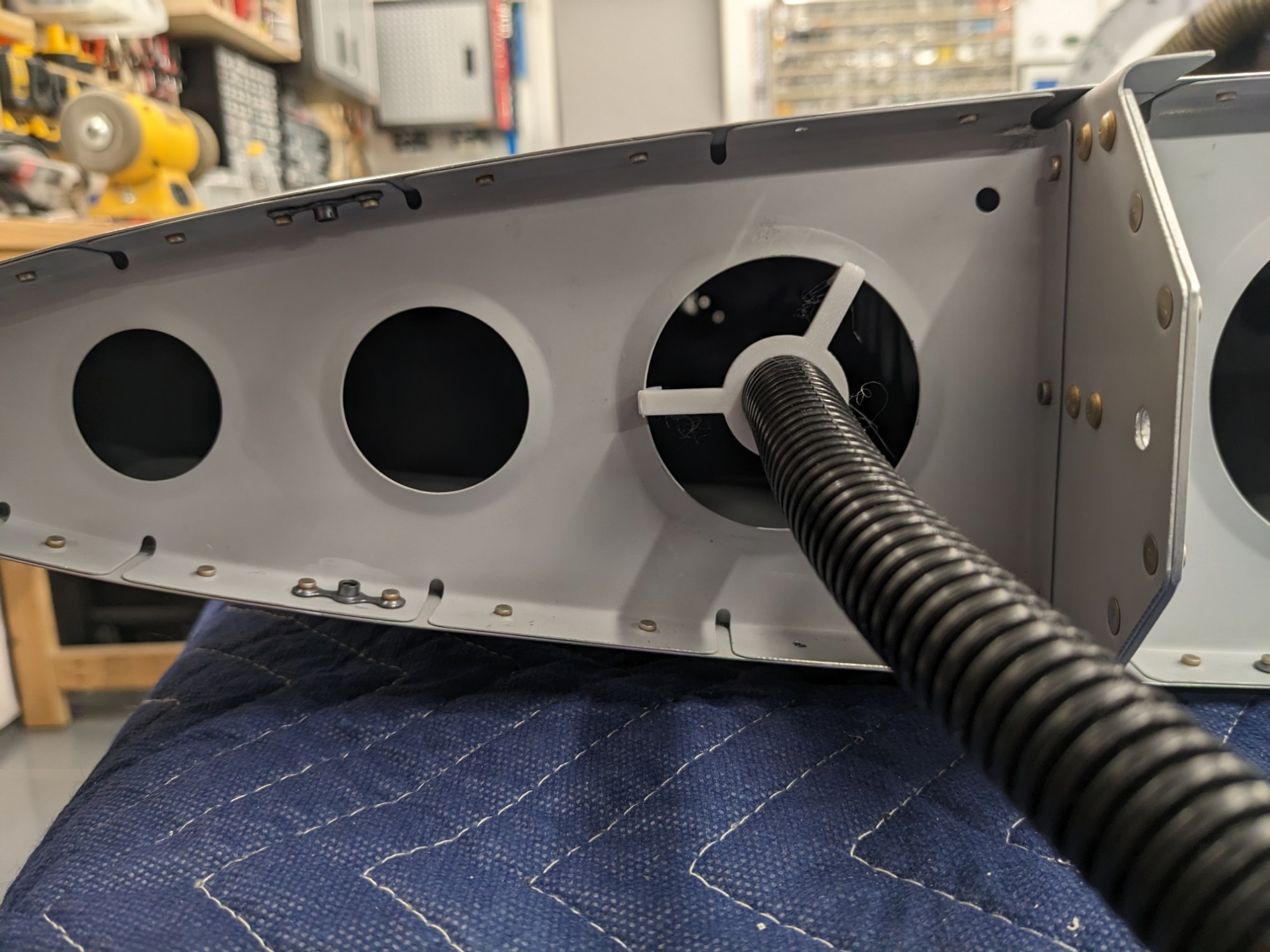
I got creative with some 3d printed polycarbonate clips that could snap into the lightening holes in the tip ribs. This allowed me to secure the conduit without drilling holes (which would be very difficult to do with limited access).
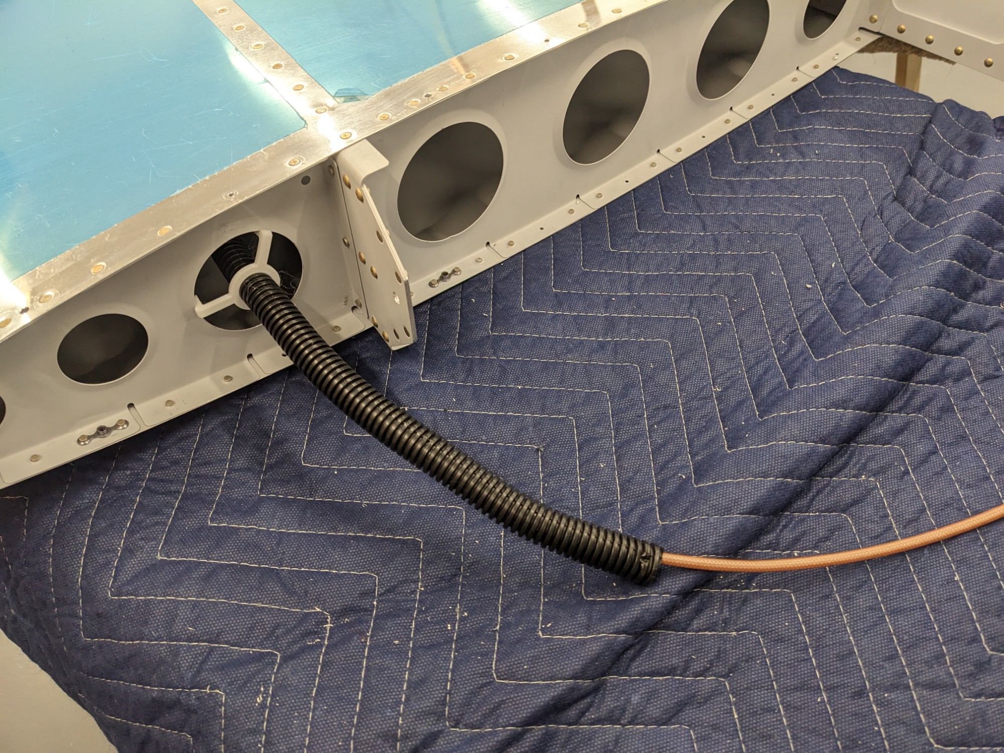
Feeding the conduit through was tricky but I was able to eventually get everything secured inside with a bracket that clipped into a tip rib lightening hole half way up the stabilizer.
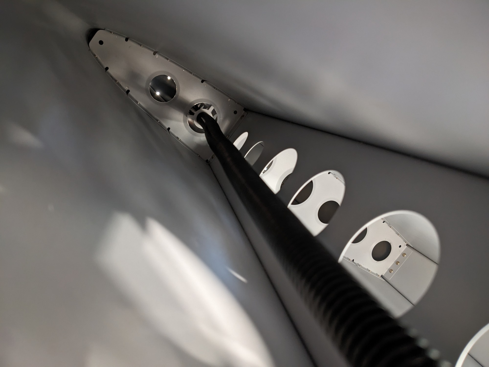
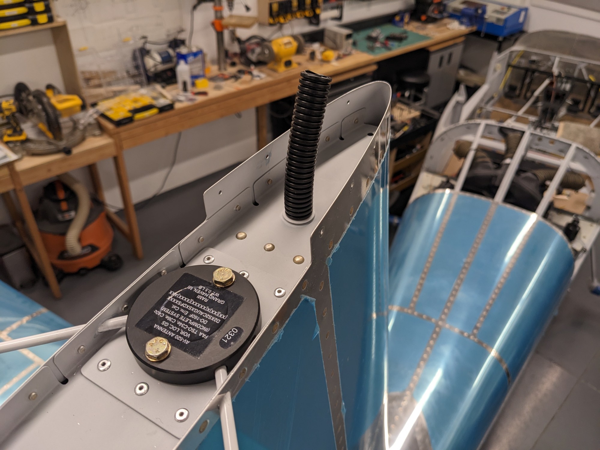
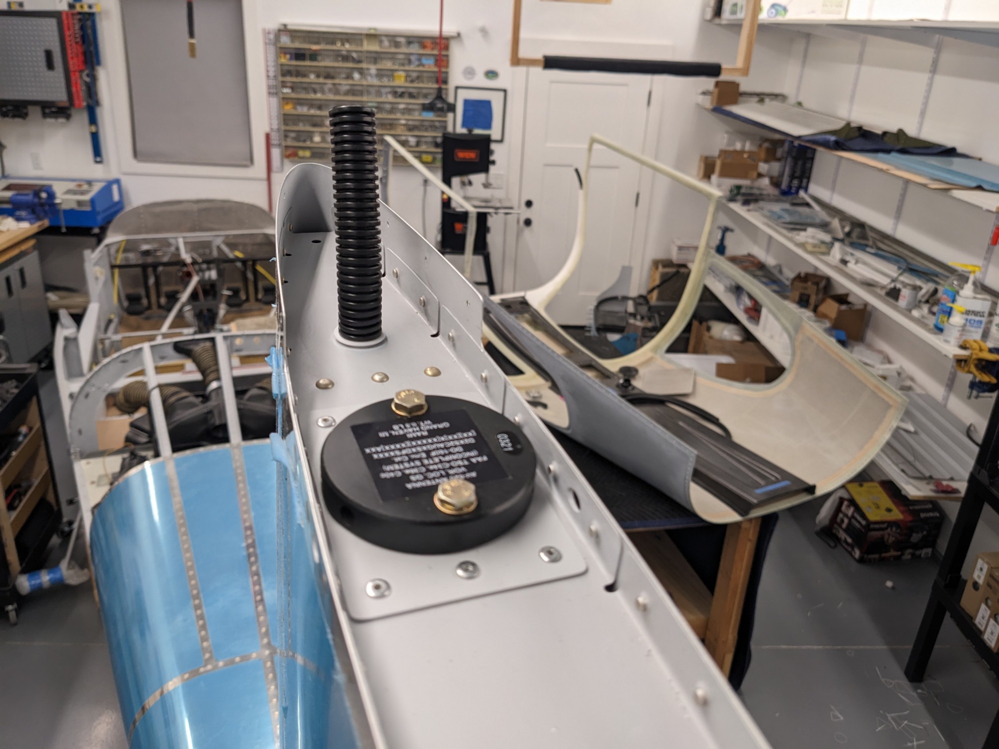
I used a 3d printed polycarbonate split washer to secure the conduit at the top of the stabilizer and to protect it from the metal edge.
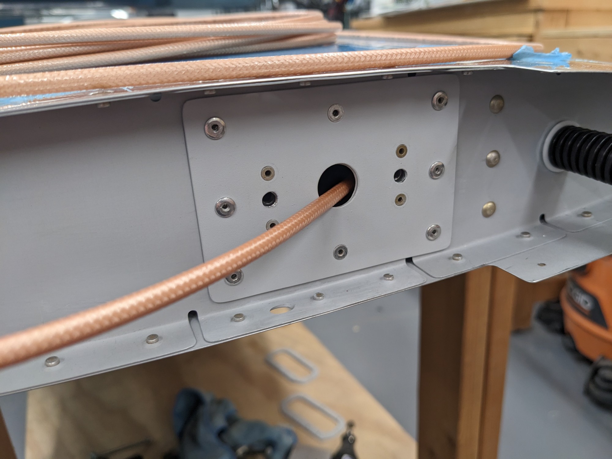
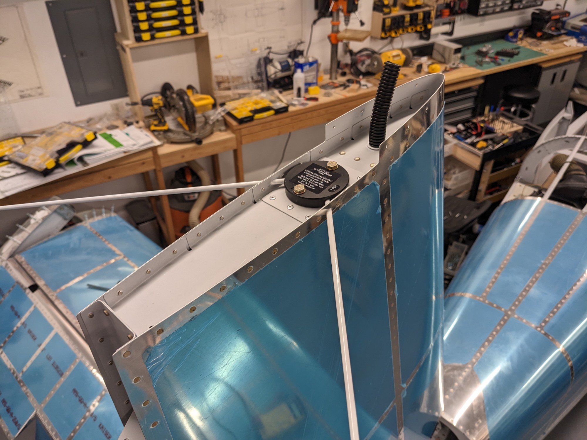
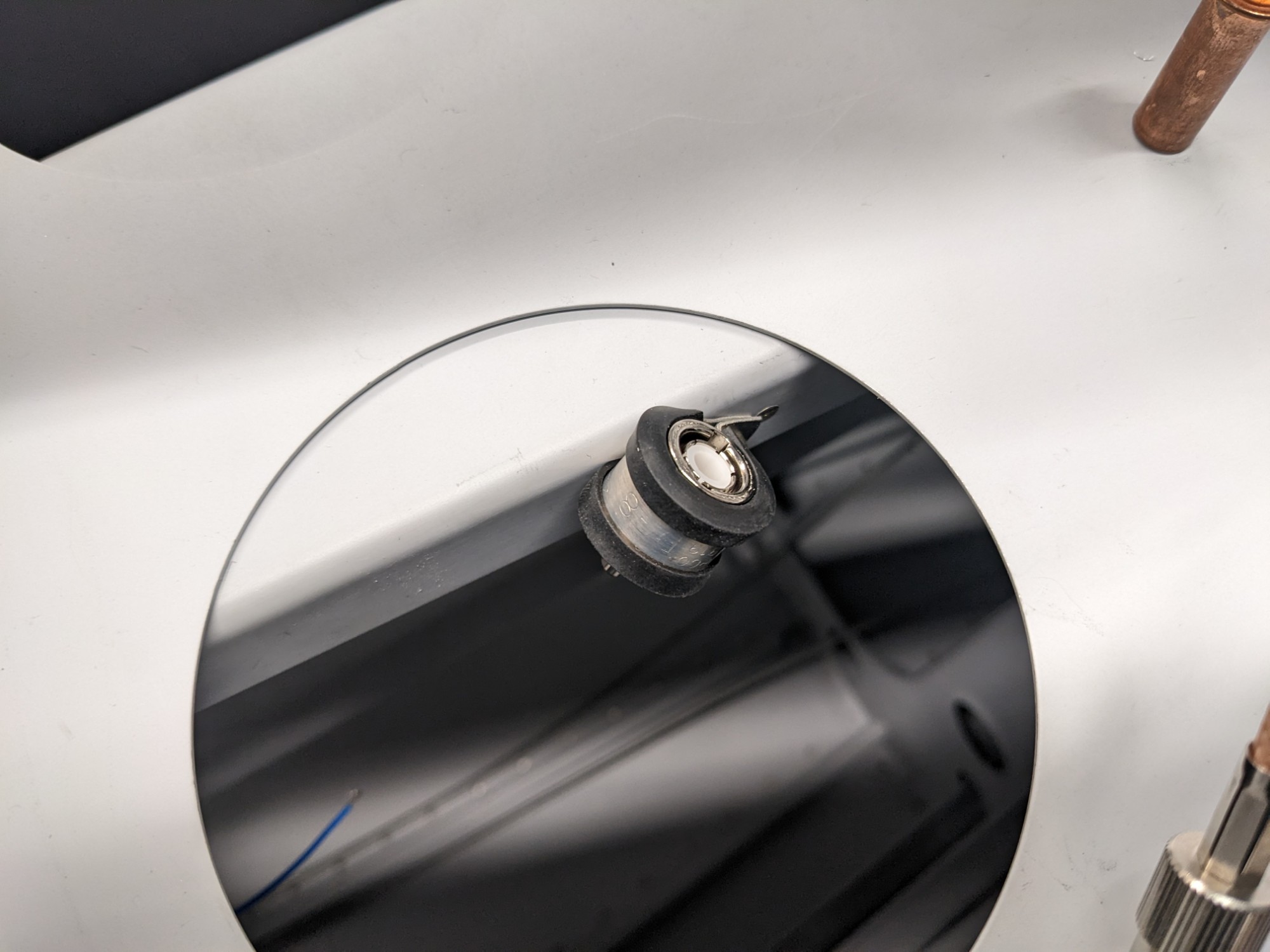
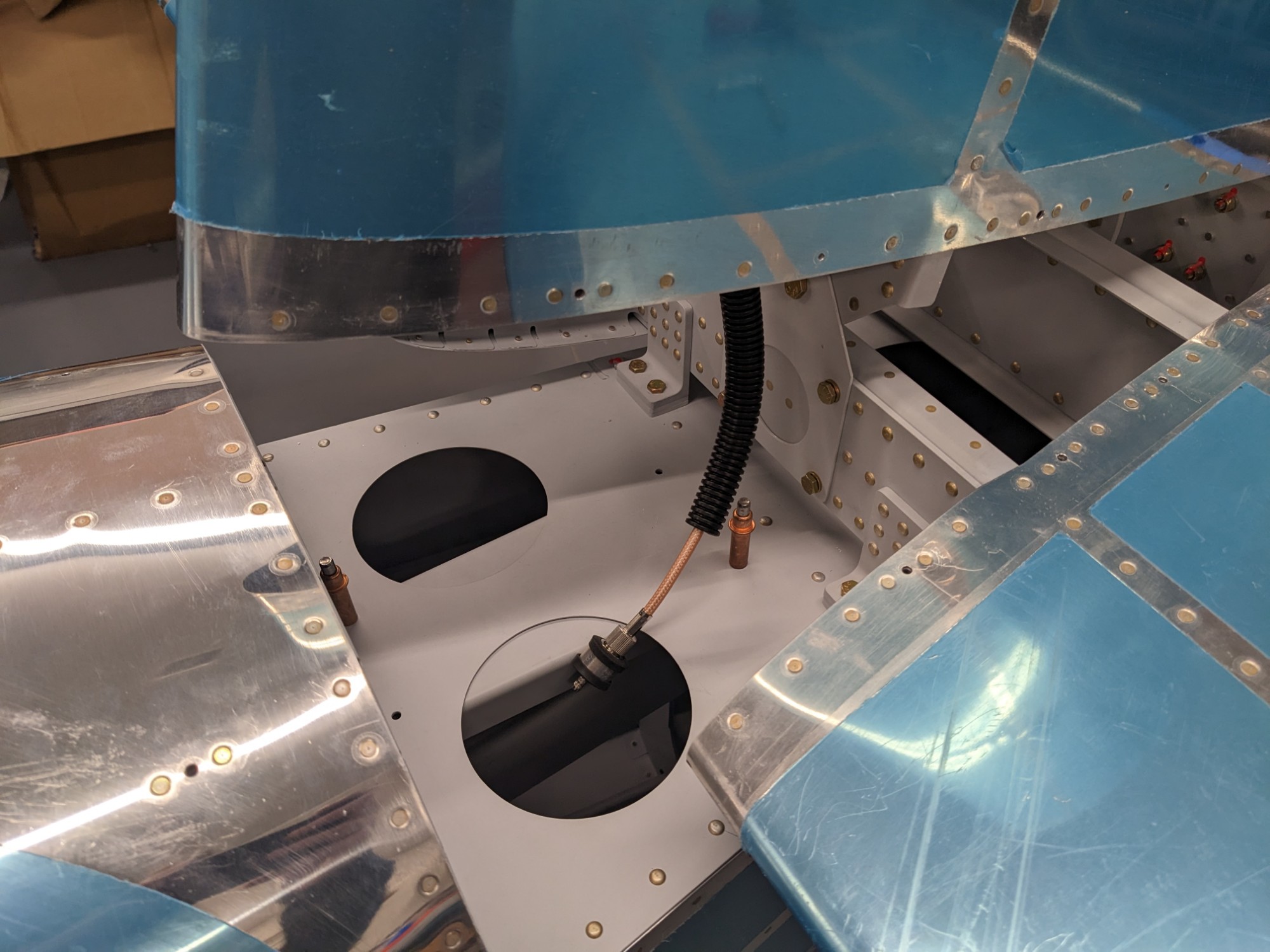
I then ran RG-400 and crimped BNC connectors on the ends. I added a female mount at the bottom so I can easily detach the stabilizer.
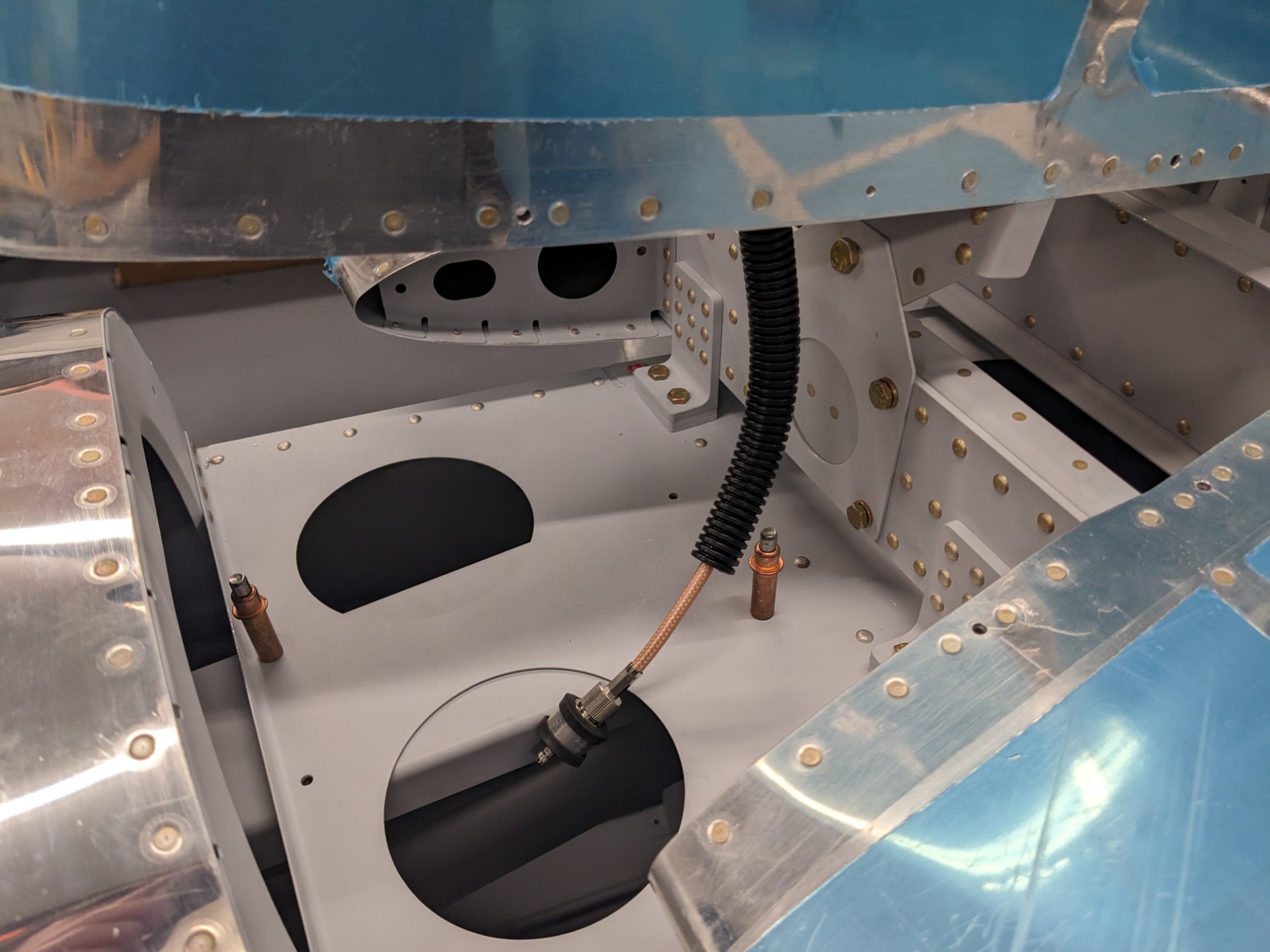
I mounted the male connector using an adel clamp attached to the trim bracket. I added a nutplate to secure it. I’ll add the coax run from here to the panel later.
I then crimped the connector at the top and test fit the antenna puck and whiskers.