I plan on flying often into Canada where FIS-B weather is not available so I am choosing to install XM in the airplane. The Garmin GA 37 antenna provides a TSO’d WAAS GPS antenna and XM antenna in a single unit (which I will connect to a GTN 650Xi and a GDL 51R respectively).
The GA 37 installation manual provides the following set of guidelines (truncated where not problematic, bolded where specifically relevant to my build):
GPS/WAAS Antennas
Because meeting all of these installation guidelines may not be possible on all aircraft, these guidelines are listed in order of importance to achieve optimum performance. Items 3a, 3b, and 3c below are of equal importance and their significance may depend on the aircraft installation
- Mount the antenna as close to level as possible with respect to the normal cruise flight attitude of the aircraft. […].
- The GPS antenna should be mounted in a location to minimize the effects of airframe shadowing during typical maneuvers. Typically mounting farther away from the tail section reduces signal blockage seen by the GPS antenna.
- (a) The GPS antenna should be mounted no closer than two feet from any VHF COM antenna or any other antenna which may emit harmonic interference at the L1 frequency of 1575.42 MHz. […]
(b) The GPS antenna should be mounted no closer than two feet from any antennas emitting more than 25 watts of power. An aircraft EMC check can verify the degradation of GPS in the presence of interference signals.
(c) To achieve the best possible low-elevation antenna gain (by minimizing pattern degradation due to shadowing and near-field interaction), the GPS antenna shall be mounted with clearance from other antennas, including passive antennas such as another GPS antenna or SiriusXM antenna. When practical, installers should use 12 inch center-to-center spacing between antennas. If 12 inch spacing is not practical use a maximum center-to-center spacing from adjacent antennas, but never less than 9 inch center-to-center spacing. Spacing less than 9 inches center-to-center results in unacceptable GPS/WAAS antenna pattern degradation.
SiriusXM® Antennas
[…] Maintain about three feet from heater, ignition, autopilot, and other control surface actuators and motors.
Maintain about five feet from fluorescent lamps, related ballast, air conditioners, blowers, strobe lights and power supplies.
Electrical Bonding
- The antenna baseplate is electrically bonded to the aircraft ground plane.
- For optimum antenna performance, a metallic ground plane or skin sized at least 7.5 inches beyond the perimeter of the antenna is recommended. If ground plane is added to the aircraft, round its edges to be as circular as practical for best performance.
In addition to the Garmin guidelines, Van’s Aircraft strongly recommends against making holes in the fiberglass cabin top.
Decisions, decisions
If I ignore the recommendation from Van’s, the best place to install the antenna would be on the top of the cabin between the doors (minus the ability to easily provide a ground plane). The ground plane is described as “for optimal performance” and I have noted that many other builders do not use a ground plane.
The best location to provide a ground plane would be to install it just aft of the cabin top but this brings it out of level, brings it closer to the vertical stabilizer, and would be within a foot of the A/C blower motor.
The other remaining option was to mount the antenna inside the overhead console, just aft of the joggle where there is more clearance and where the antenna is accessible via the aft overhead console access panel. Nothing in the manual indicates that the antenna cannot be installed beneath a composite skin (and I have noted that many others have done this, including under the fiberglass cowl). I won’t be using metallic paint. I can also provide a ground plane, but not full size, in this location.
I ultimately decided to give myself two options, with the second being an easy change if I have problems with the first option during flight testing:
- Install the antenna inside the overhead console. This has no impact on the cabin top and it would be easy to move the antenna from this location later if necessary. This also provides the advantage of having one less external antenna.
- Install the antenna on the outside of the overhead (either between the doors or slightly further aft. This location is accessible via the access panels in the overhead console if I need to change to this location. I prefer to avoid this location to avoid drilling holes in the cabin top but have also noted that many others have done this.
Installation
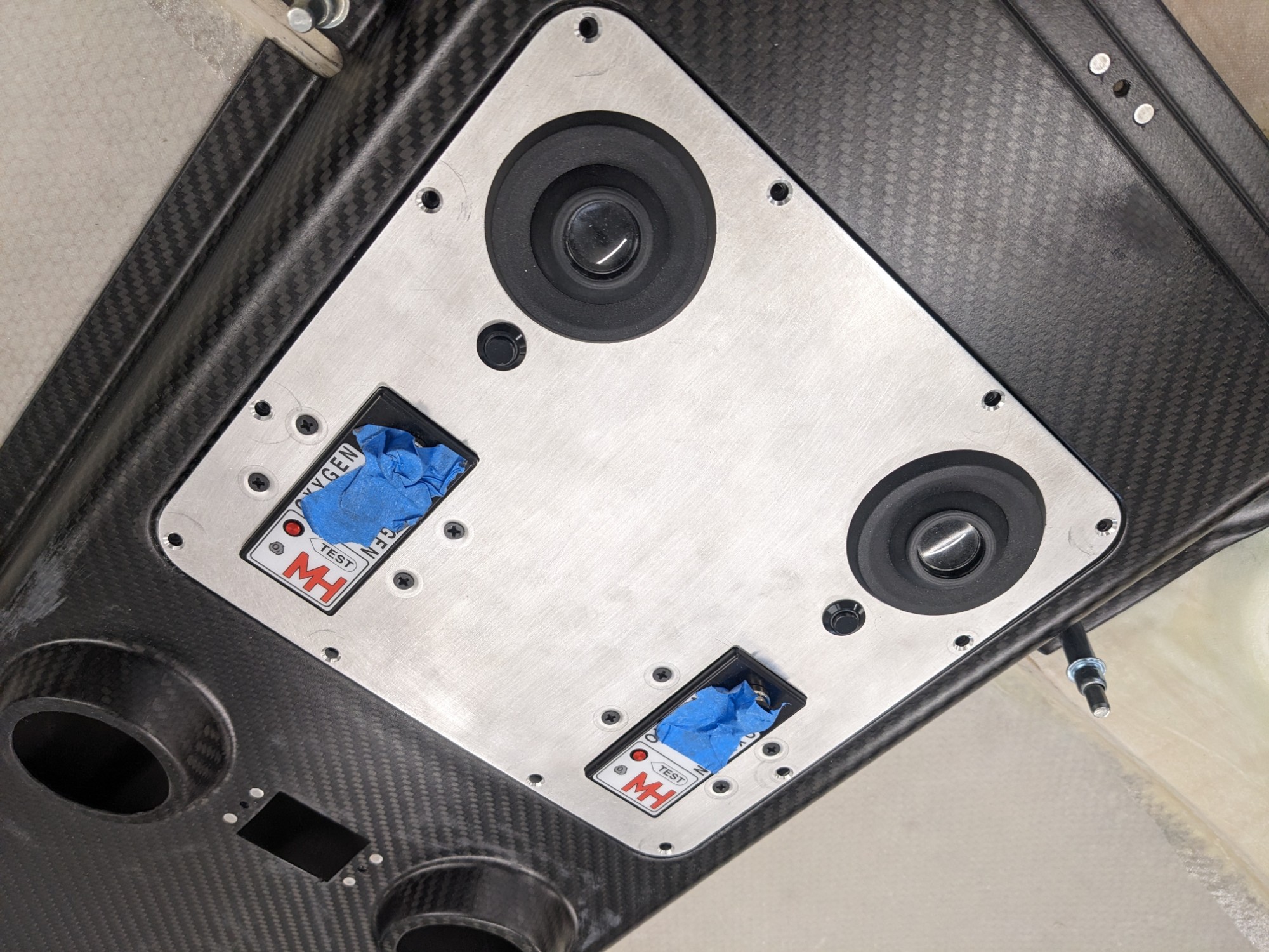
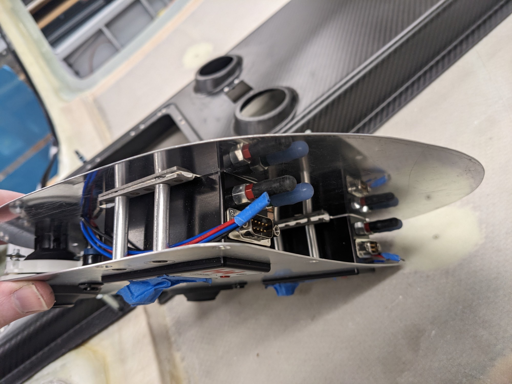
I had planned for this possibility when installing the oxygen distributors, so I left sufficient horizontal space between them to fit the antenna above the access panel. The vertical space is tight, even with right-angle connectors for the antennas. I added a curve to the access panel to give me a bit more room. The curve is barely noticeable and doesn’t look out of place.
I’m unclear if the solenoids inside the oxygen distributors will be problematic but they are small and inside a grounded metallic housing. I’ll test this later to be sure that they don’t cause interference while operating.
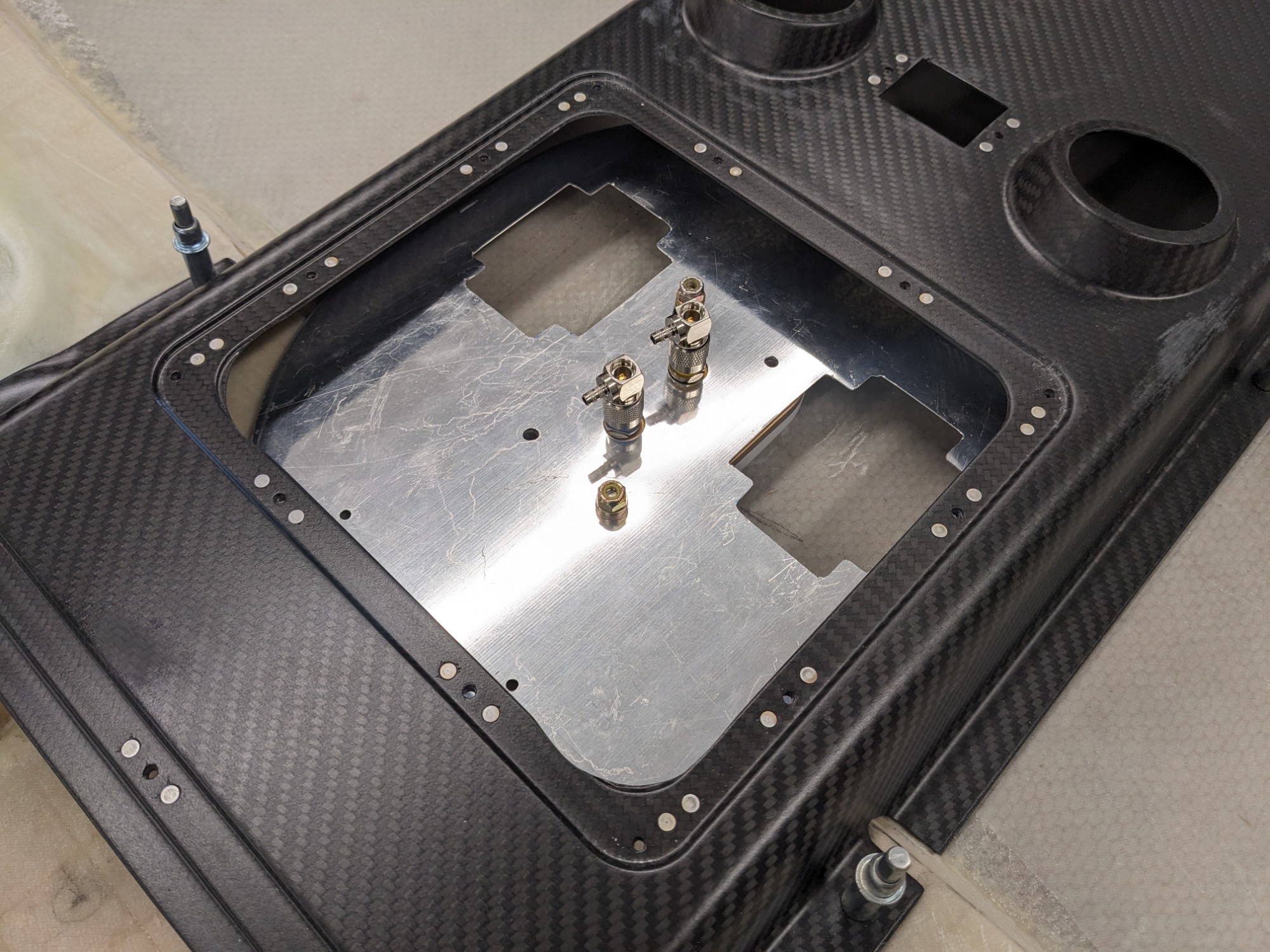
I created a ground plane (and mounting surface) from some scrap aluminum and made it as large as possible such that I could insert it via the opening in the overhead console. I removed the seal flange on the console to make more room but I think I can air-seal this area without it by 3d printing a TPU gasket if needed.
I had to create cutouts for the mounting brackets of the oxygen distributors. These brackets/covers end up being close to flush with the ground plane when the parts are sandwiched together.
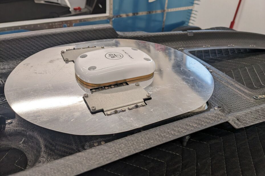
The sandwich is installed by inserting the GPS antenna assembly first, then securing it with the access panel assembly.
These pictures show the position of the assembly when installed in the overhead.
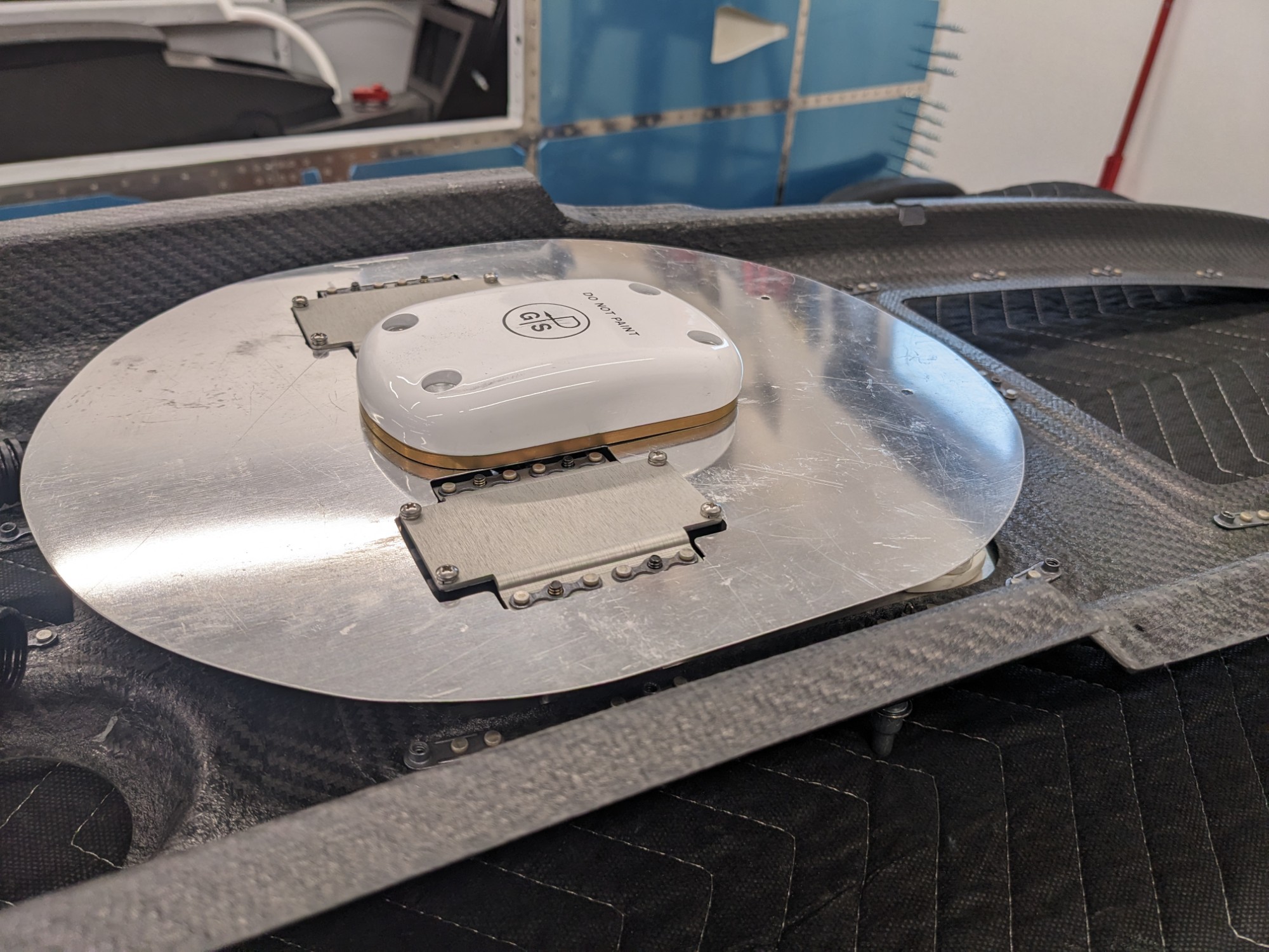
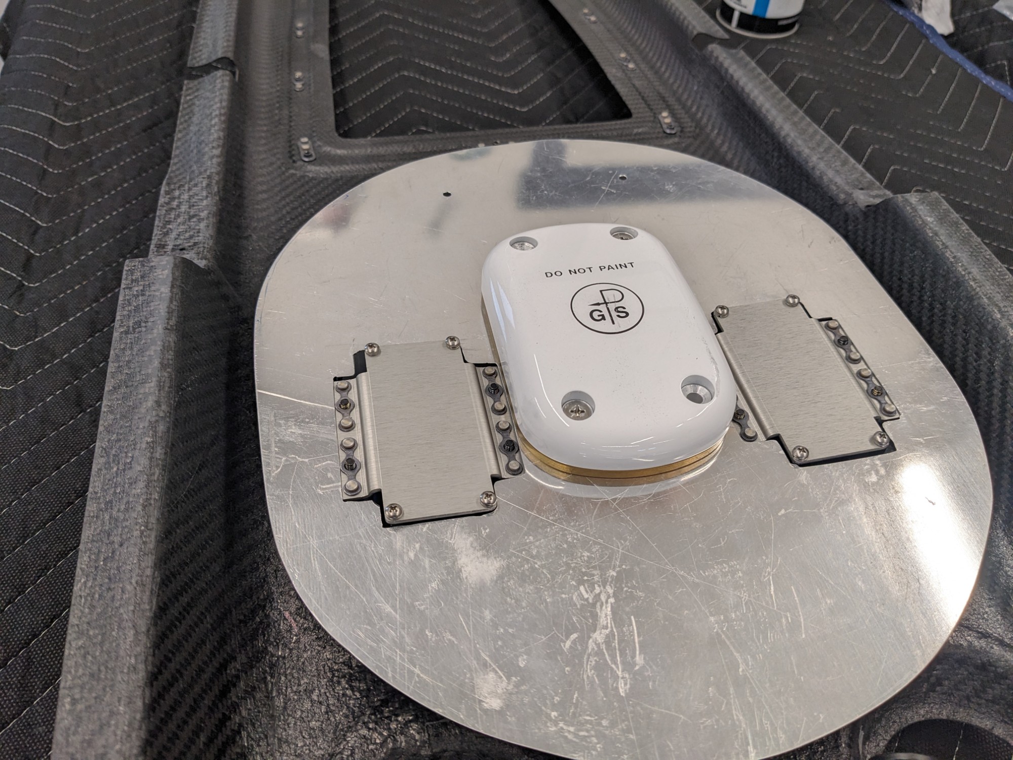
The ground plane clears the joggle in the cabin top on the forward side by about 1/8″ (this photo is taken looking aft from the forward access panel in the overhead when the console is attached to the cabin top). I’ll add a ground wire to one of the antenna mounting screws with a ring terminal to ensure the antenna has a solid connection to aircraft ground.

The final installation is clean and secure. I’m hoping this works well in practice.