I have been working on the design of my instrument panel while waiting for various kit parts that are on backorder. I have also been working on diagramming my electrical system in KiCad.
Van’s provides a CAD model of the upper forward fuselage structure so I used that as a starting point to build out a 3D model of the panel in Onshape.
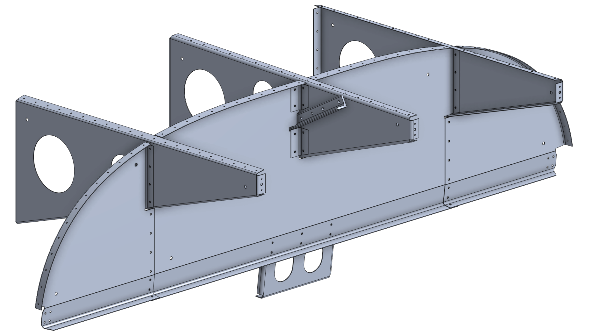
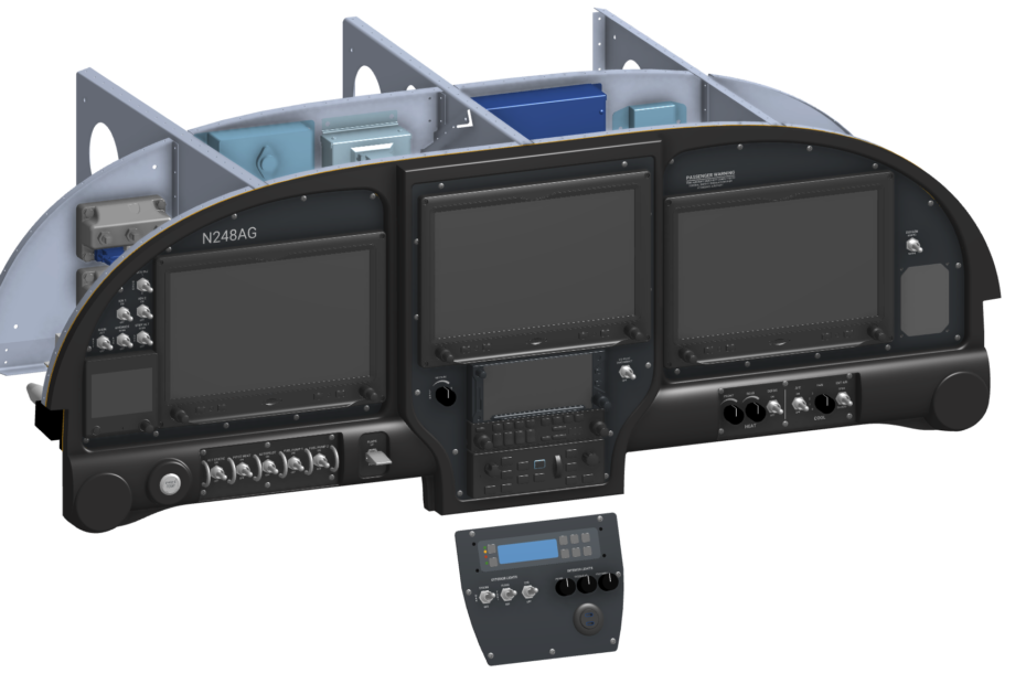
Aerosport does not provide a CAD model for the 310 carbon fiber panel, so I mocked up the rough dimensions using the panel insert drawings that they provide as a starting point. My intent was to mock up the primary dimensions of the panel so that I would be able to accurately position components and check for interference.
The following previews are not final layouts but illustrate my current thinking on the layout of components and switches. I’m writing my Pilot’s Operating Handbook (POH) concurrently to help inform the positioning of switches on the panel.
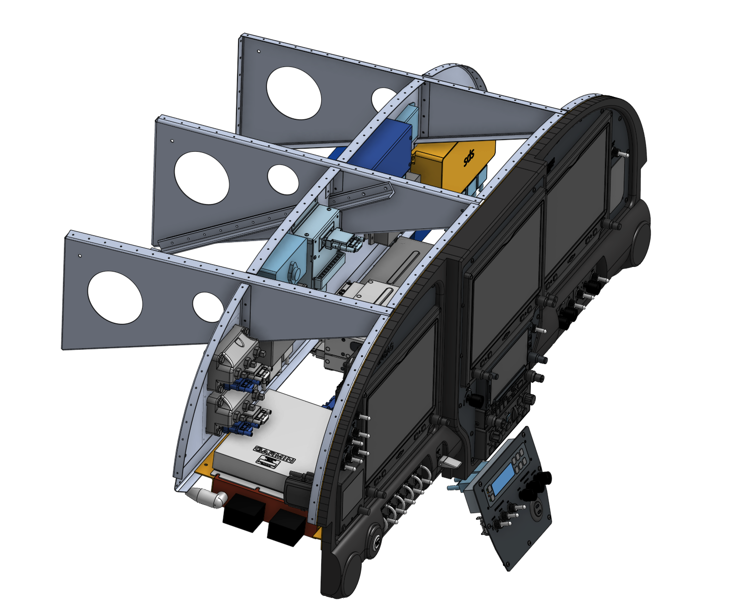
My primary panel avionics will include three G3X Touch displays, a GTN 650 IFR navigator, a GMA 245 audio panel, a GMC 507 autopilot controller, and a backup G5.
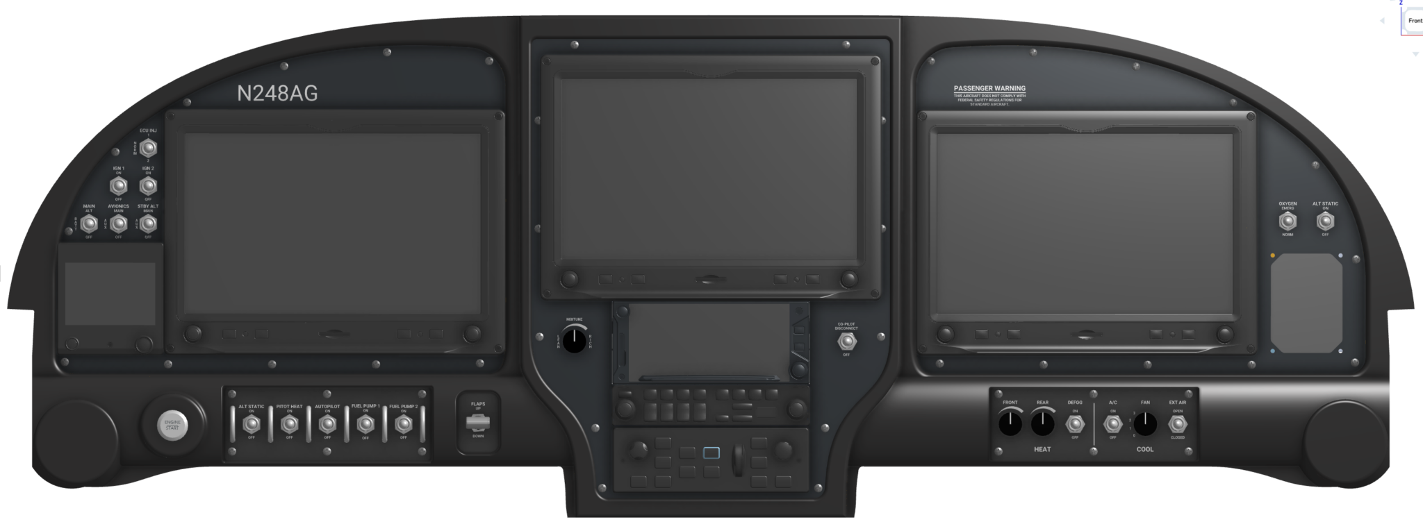
The SDS EFI controller will be mounted in the lower panel area, just ahead of the center console throttle quadrant and fuel selector valve.
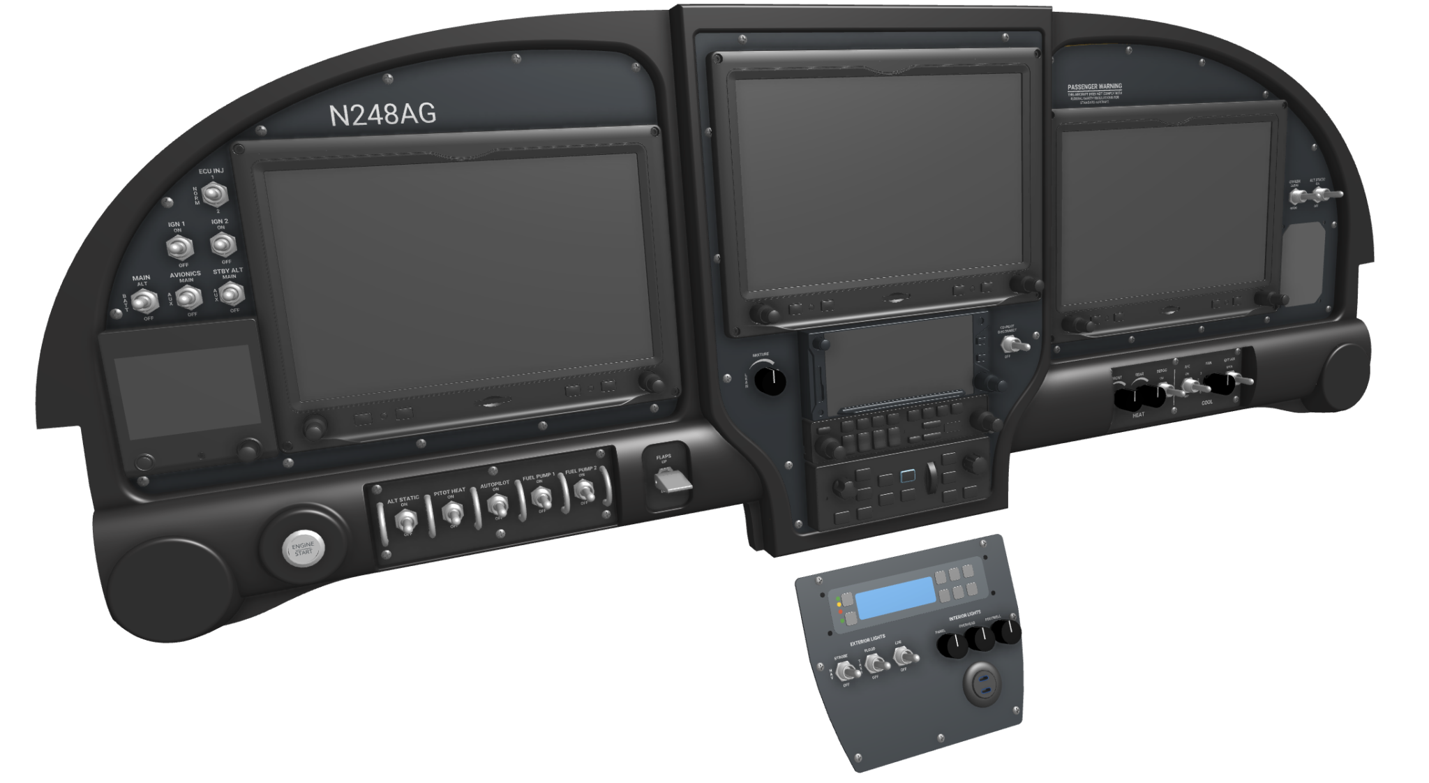
I haven’t completely dialed in my switch positions yet but my goal is to keep the switches that typically won’t be moved in flight out of the control stick area (specifically the switches for the electrical system and the switches that drive the electronic ignition and injection).
My electrical system is dual-bus (dual battery, dual alternator). The switchology is designed for simplicity (no switches to twiddle to fail over to a backup power source) and for least-surprise (engine continues to run when the electrical system switches are turned off – i.e. the smoke in the cockpit scenario).
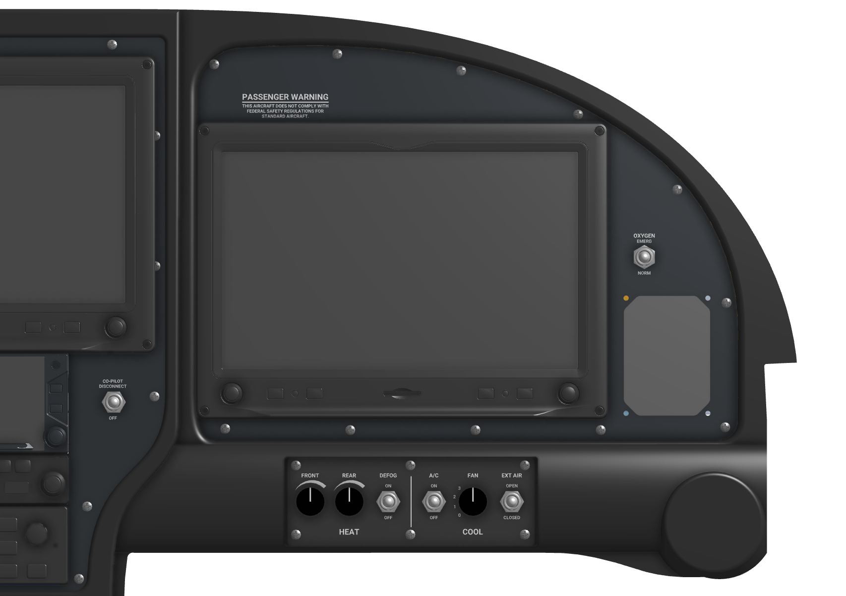
The right side of the panel houses the climate controls and the oxygen controller. I have a few more things to add on this side of the panel (ELT controller, etc.).
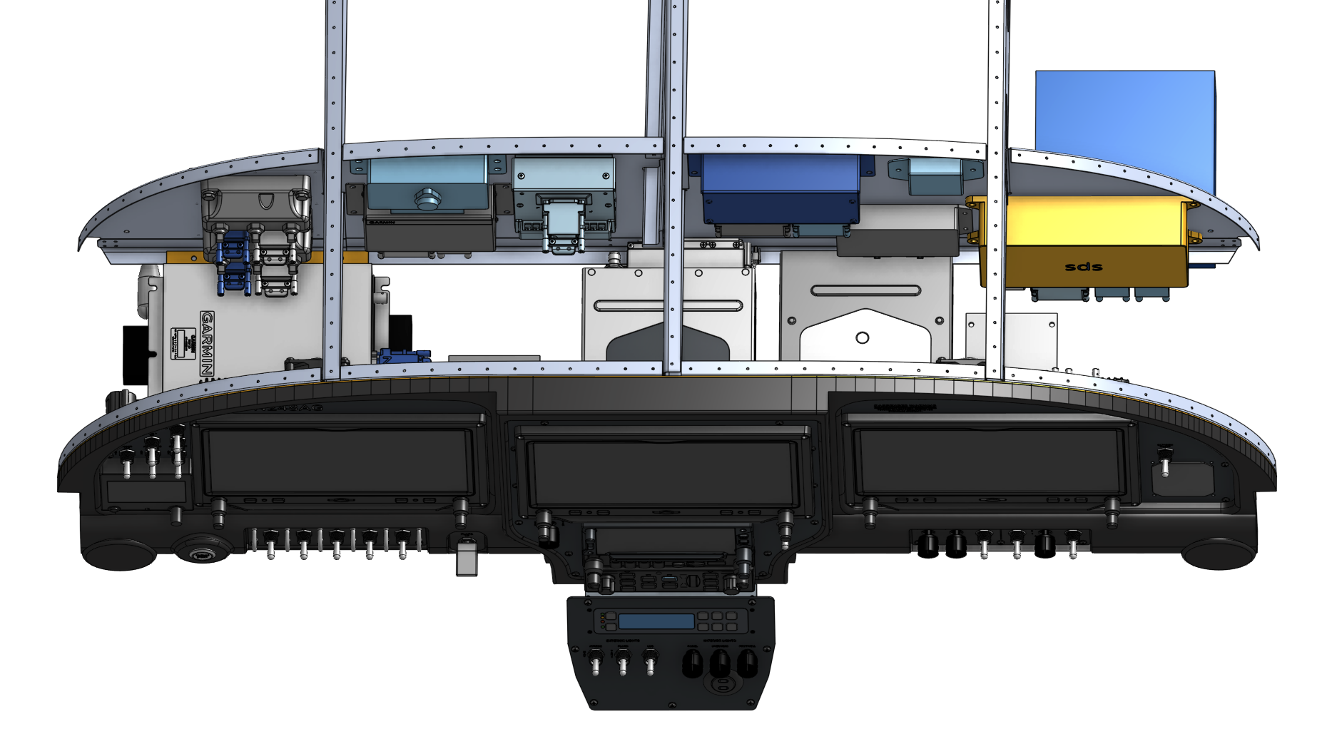
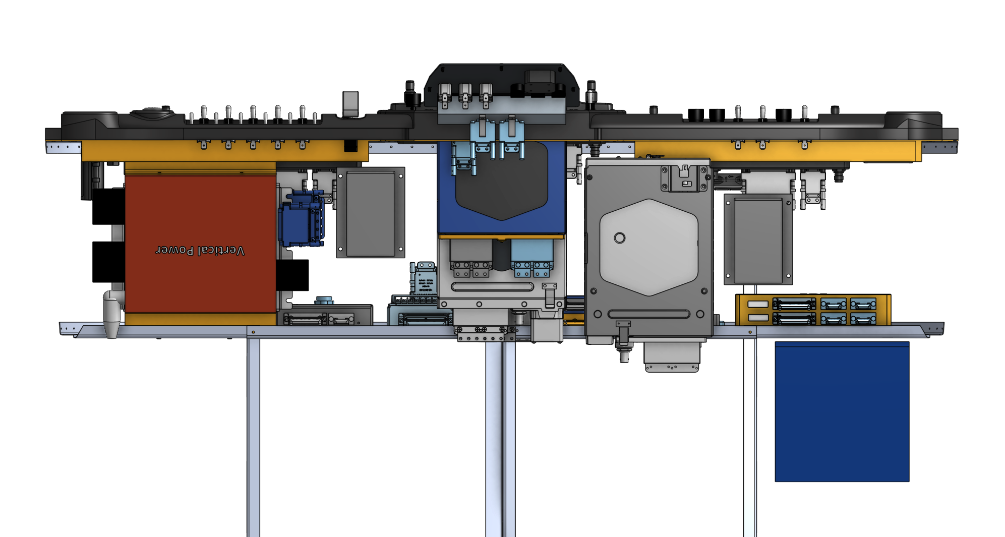
The most challenging part of the design has been the jigsaw puzzle of equipment that is mounted behind the panel. I’m attempting to optimize for the following:
Maintenance accessibility – If possible, I don’t want anything mounted behind the subpanel. I plan to assemble in-place (not upside down on the bench) so that I don’t allow myself to create an installation that is difficult to maintain. Additionally, I want to have easy access to fuses (although I don’t intend to replace fuses in-flight). I am planning on using Eaton Bussman ATM fuse blocks that wire from the rear of the blocks (so that fuses can be accessible below the panel).
Layout efficiency – I’m trying to keep primary connections proximally close to each other and I am trying to separate high-current loads that pass through the firewall from sense/signal connections.
The CAD model has been really helpful for trying out different locations and ensuring that there is no interference between components. Garmin provides CAD models for all of their experimental avionics (including the connectors) which has been extremely helpful.