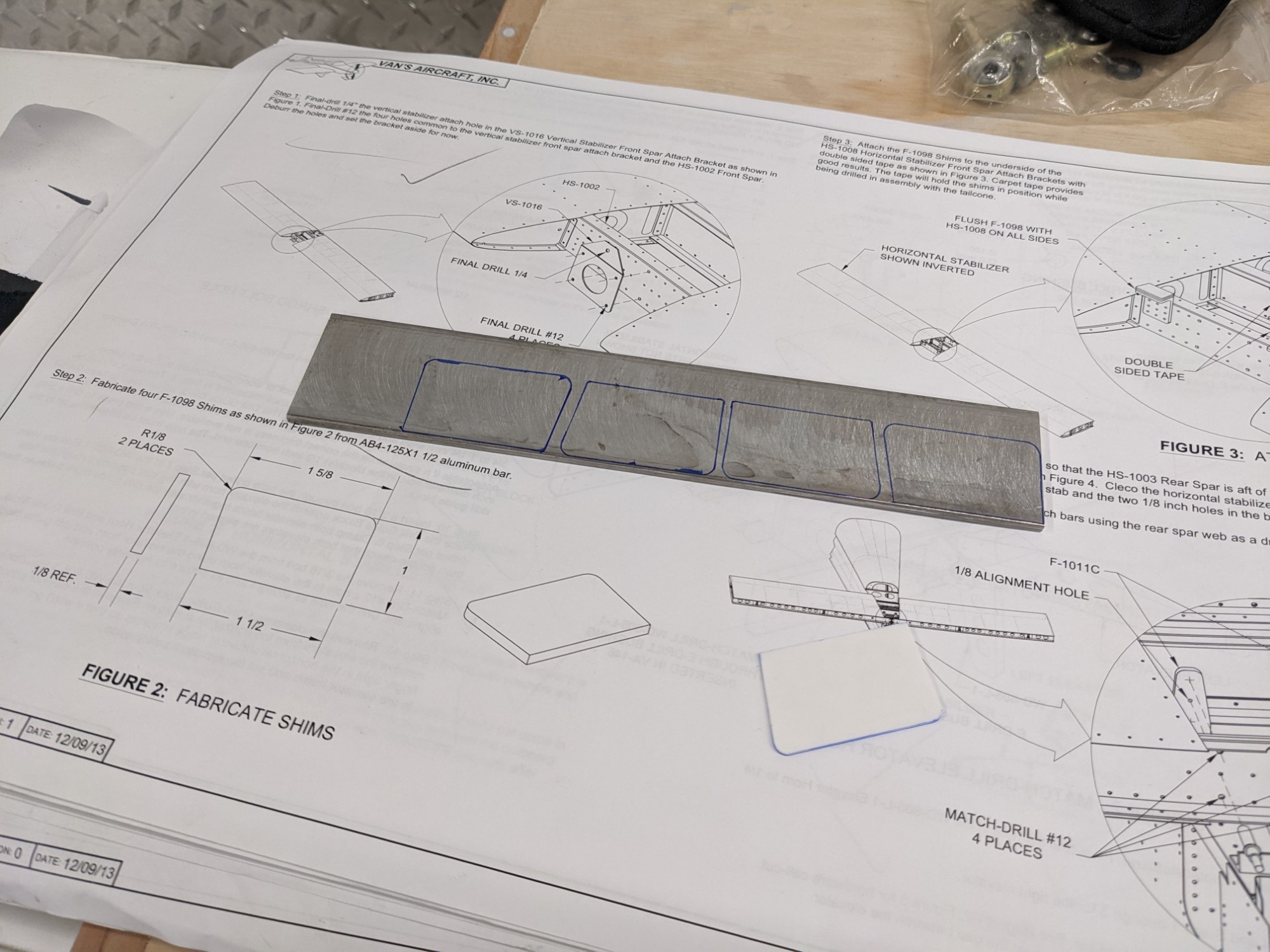
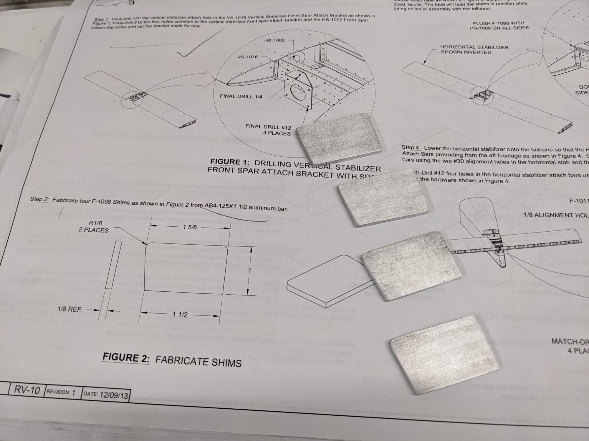
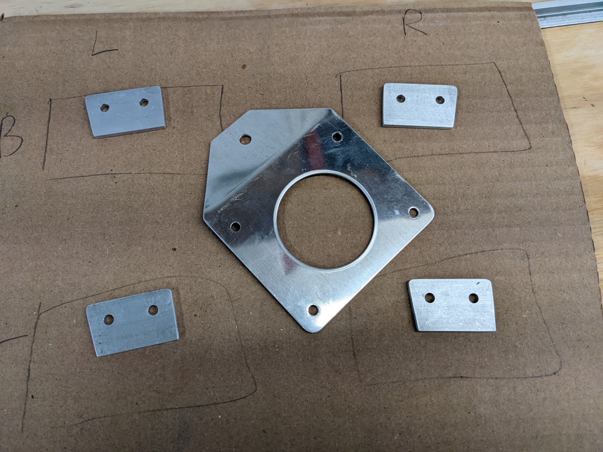
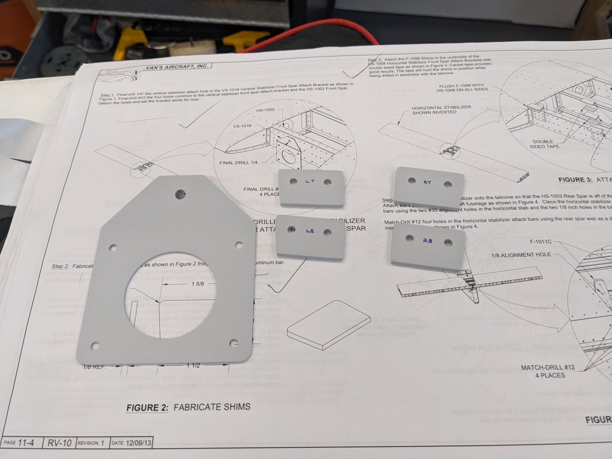
Shims are required to position the forward edge of the horizontal stabilizer. I rough cut them on the band saw and shaped them on the disc sander.
I then used VHB tape to attach the shims to the stabilizer to hold them in place while match drilling.
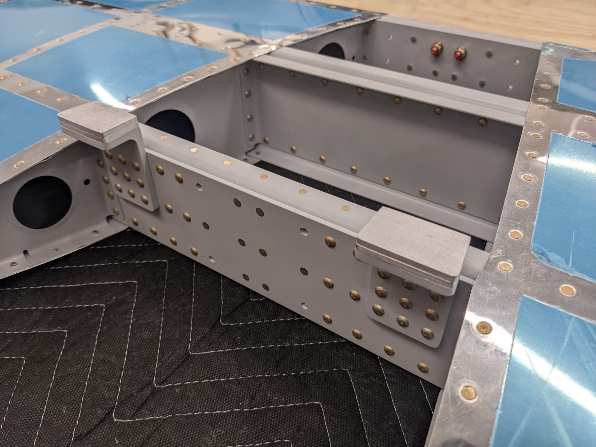
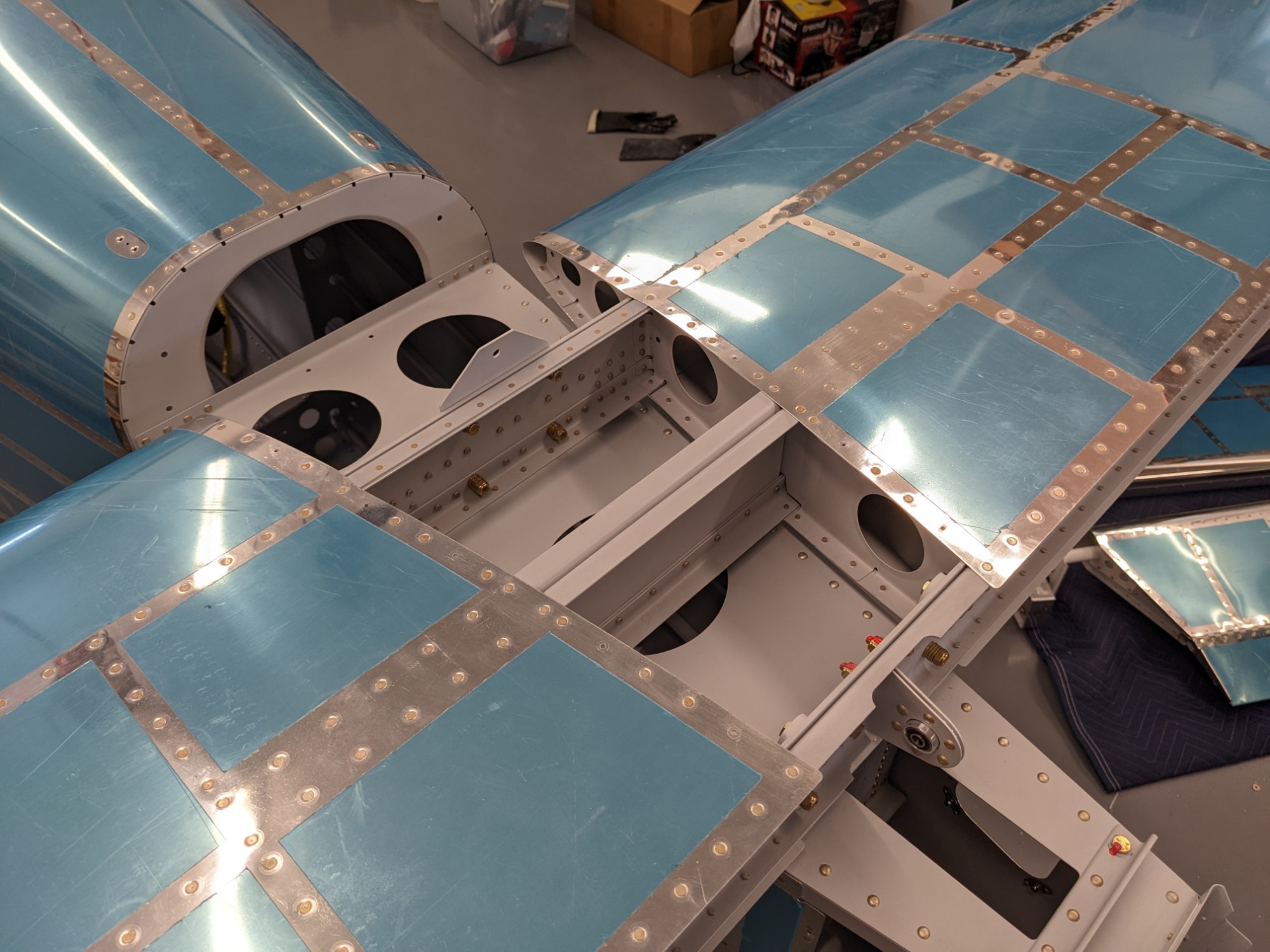
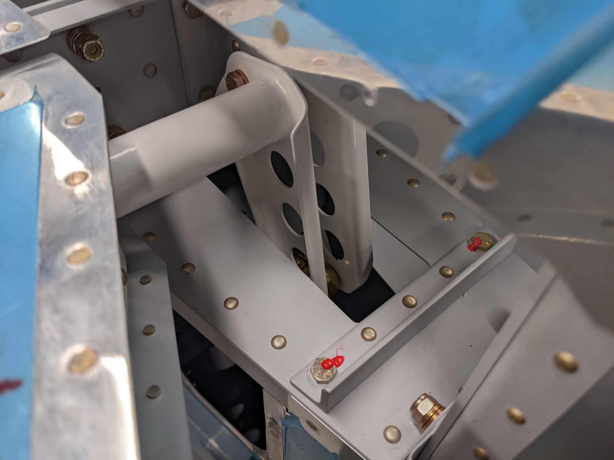
I then match drilled the holes in the rear spar and through the forward attach brackets. I took plenty of time with these to get the holes as straight and clean as I could.
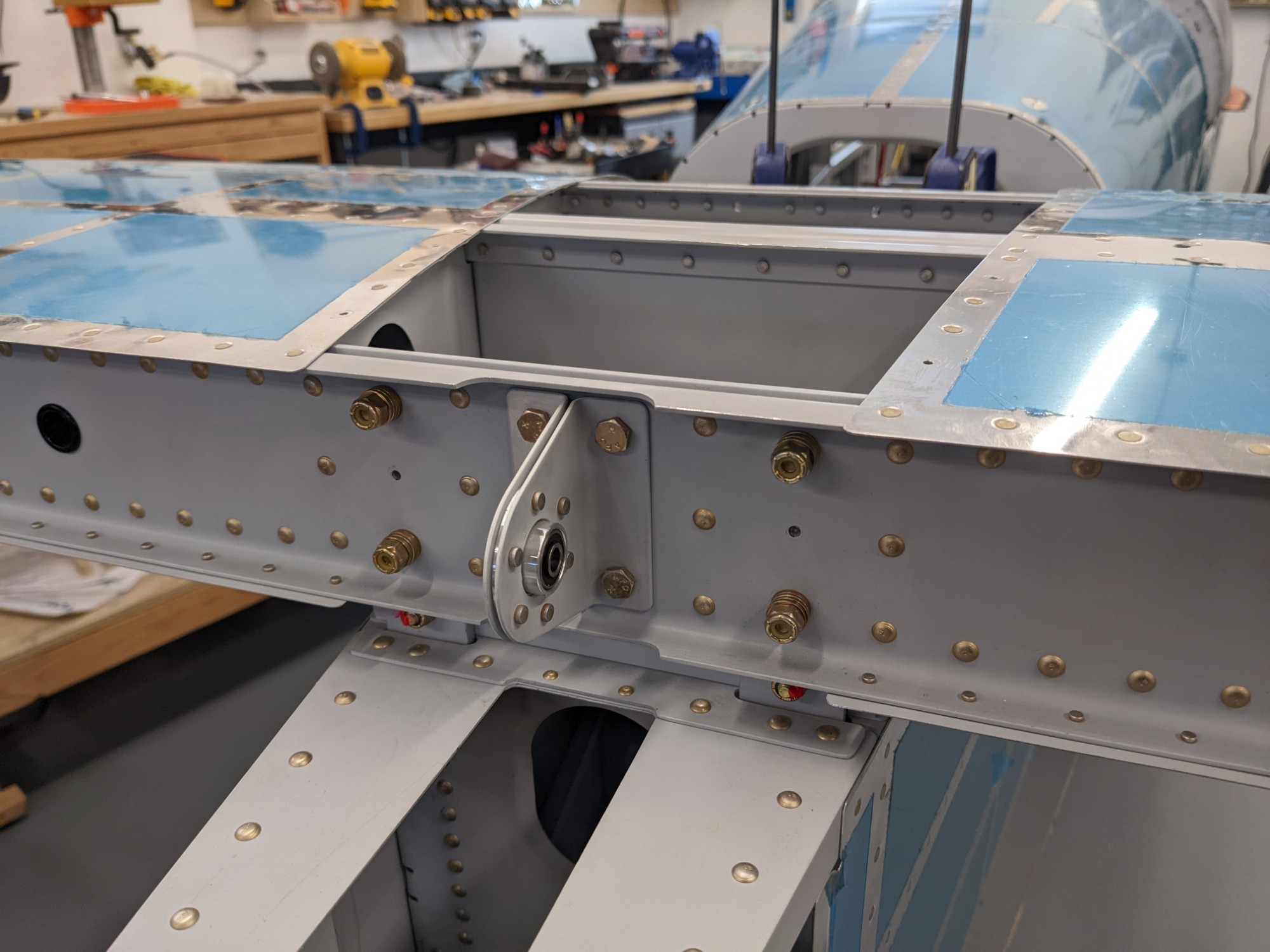
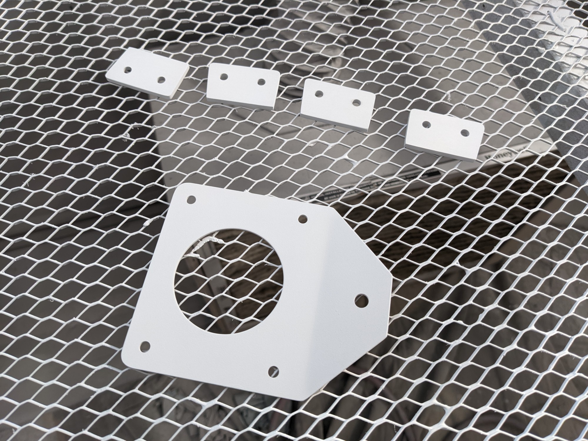
I then deburred and primed the parts and bolted them into place.
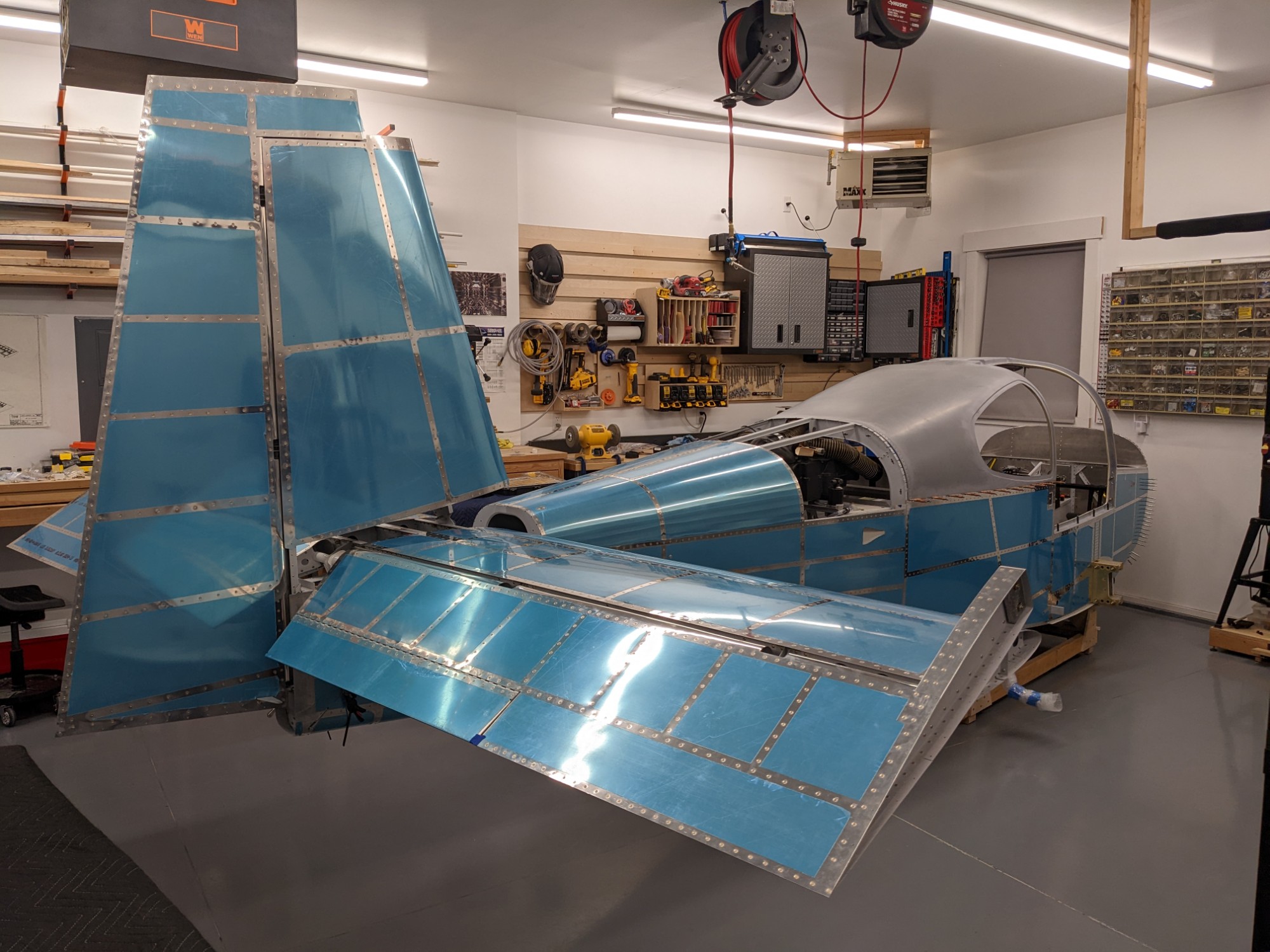
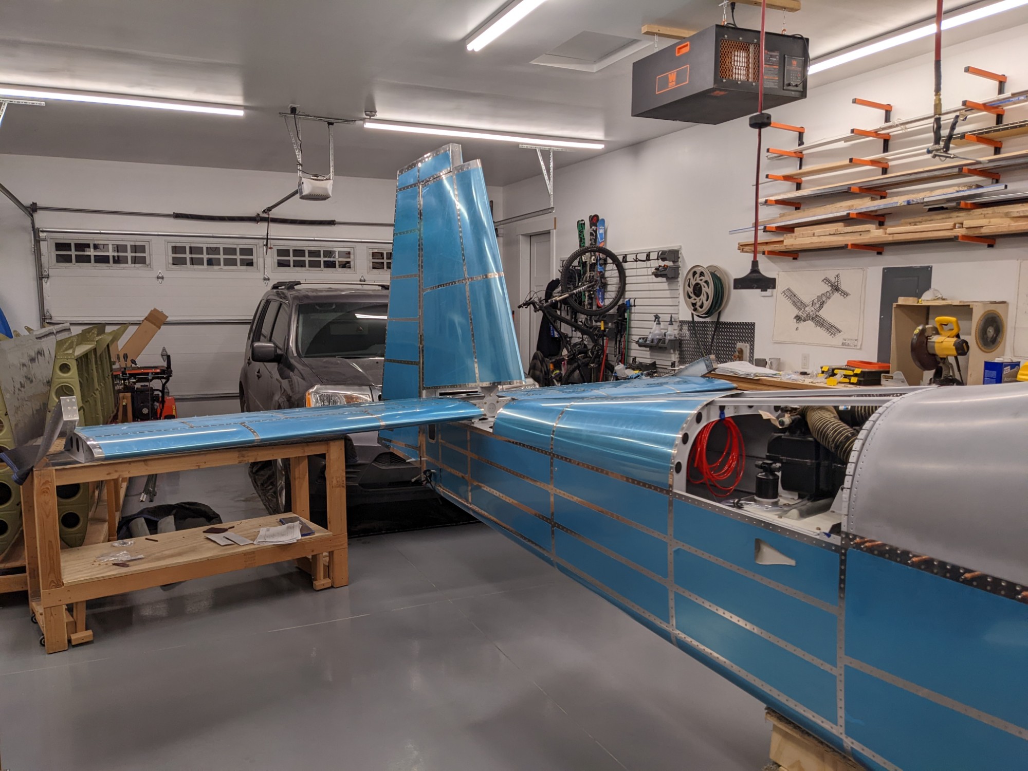
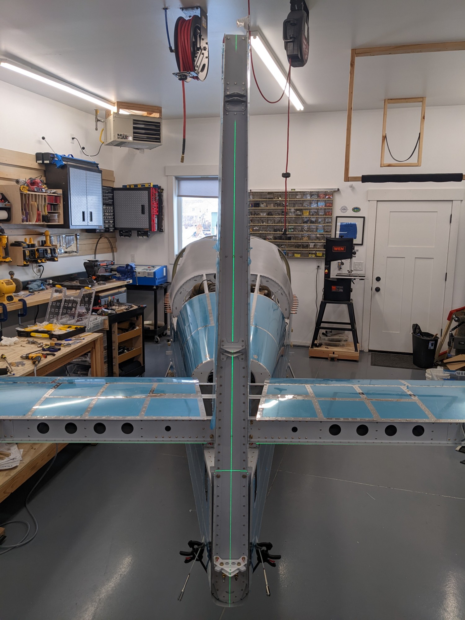
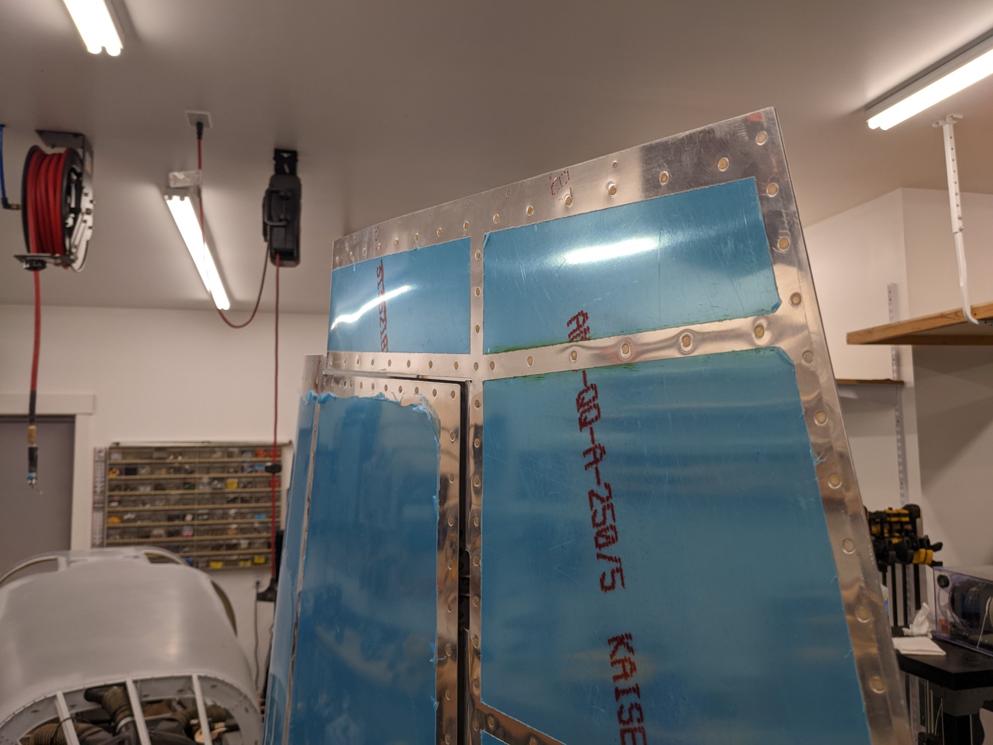
I then bolted the vertical stabilizer into place using the top two holes. I triple checked the alignment and sanity checked it with a laser level before match drilling the final holes.
Next up was mounting the elevators. The hardware was much trickier to install with much more limited access.
The elevator stops ending up giving me the necessary range of motion with no modifications needed.
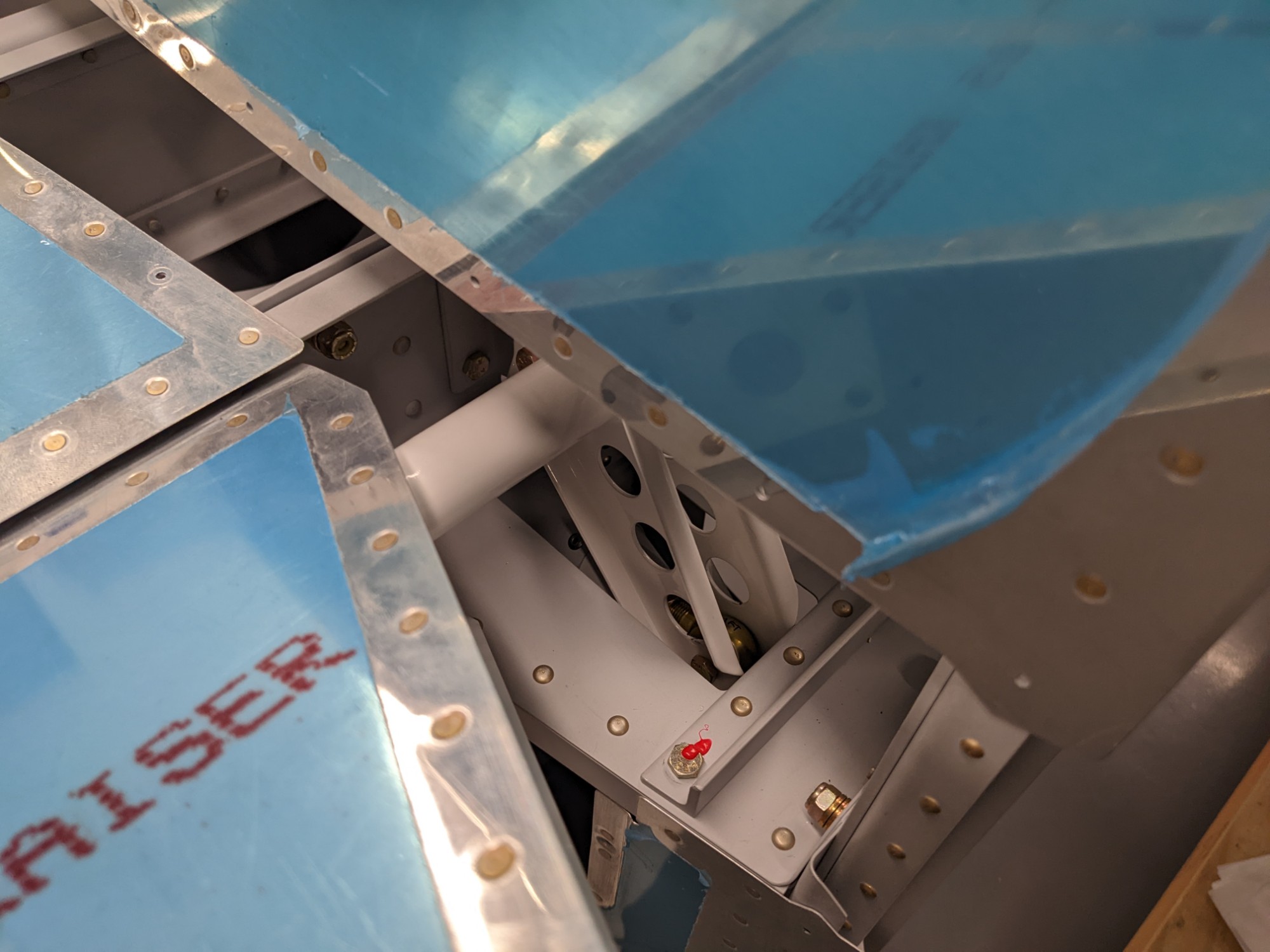
I had previously assembled the elevator pushrod so installing it was a quick task. I 3d printed a triangle at 91.4 degrees to set the position of the elevator bell crank. The elevator moved smoothly from stop to stop with the control stick.
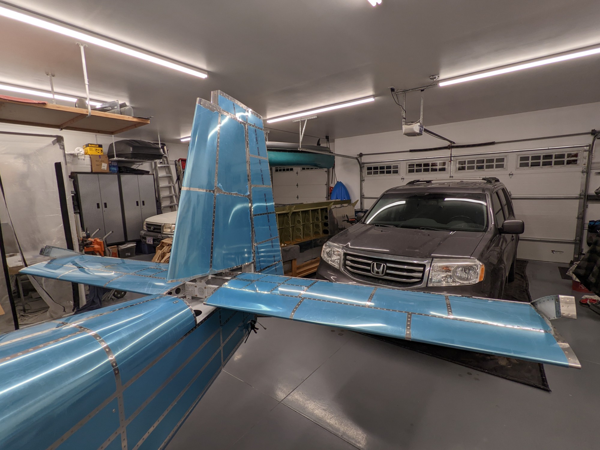
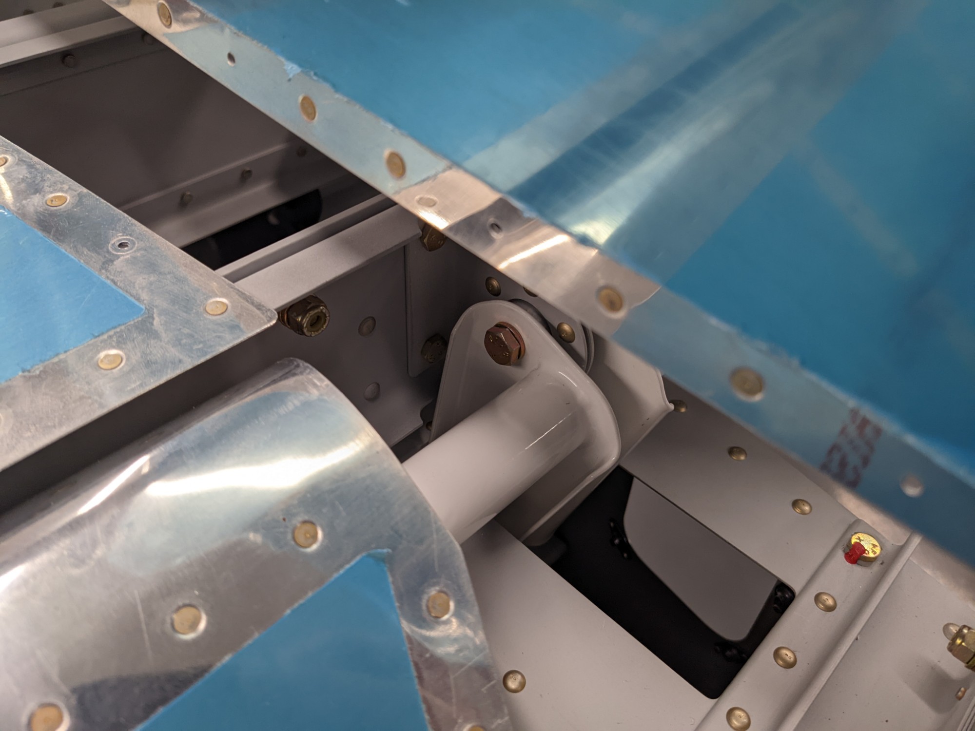
I then installed the rudder.
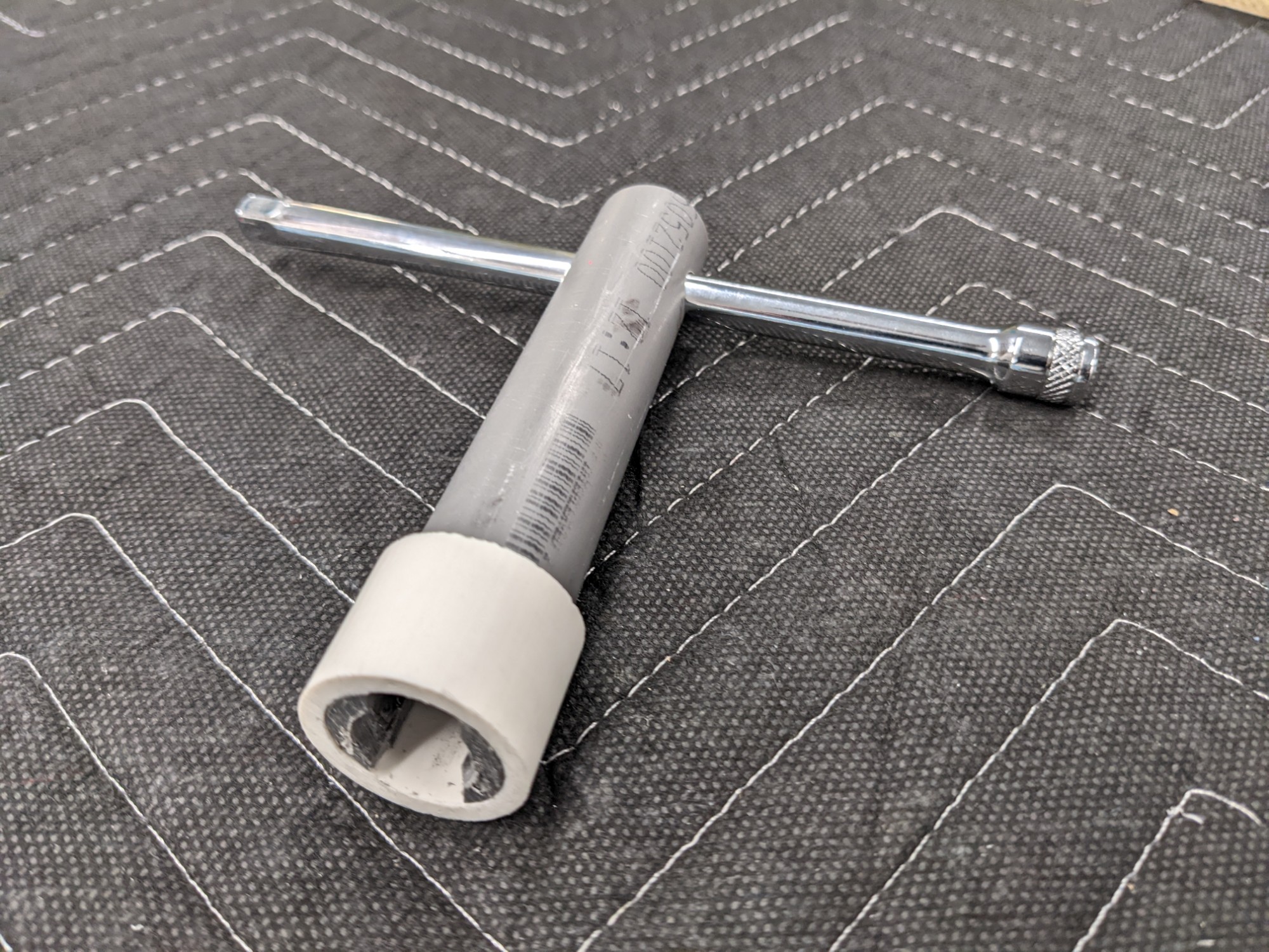
I made a tool to insert the rod end bearings.
The rudder had slightly too much right deflection and not enough left deflection so I tightened the rod end bearing by half a turn and I removed some of the left stop. I was able to get the specified deflection in both directions after adjusting.
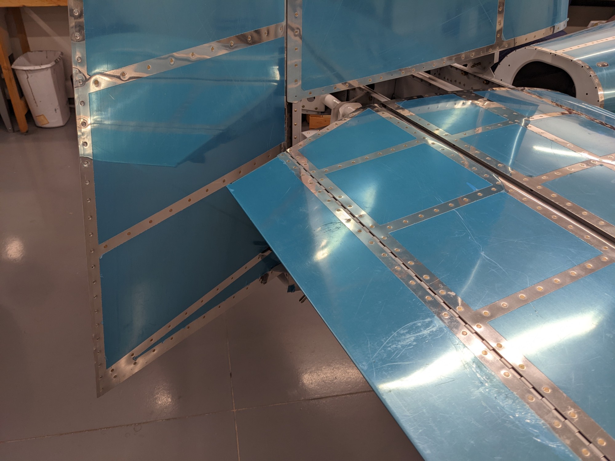
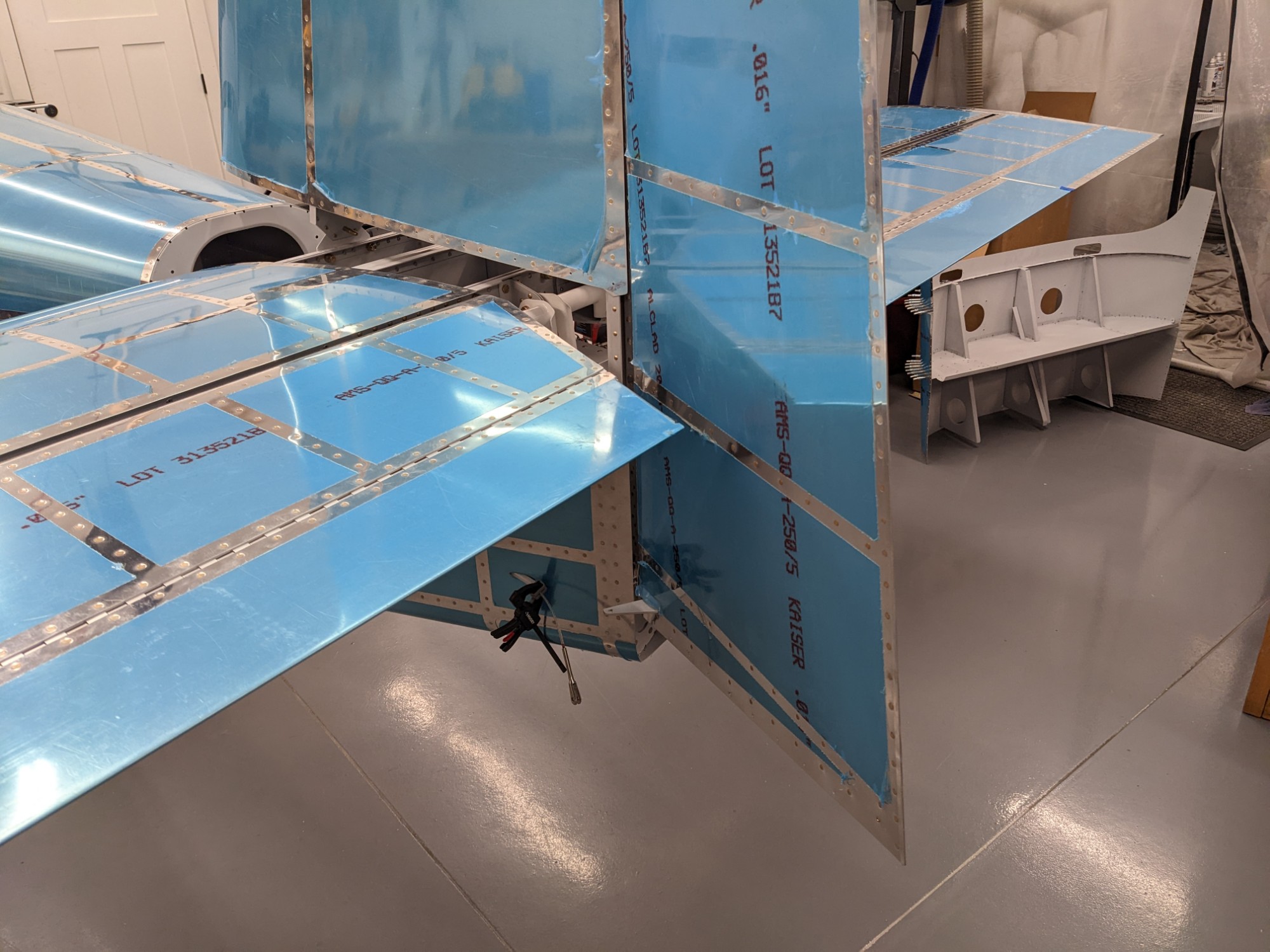
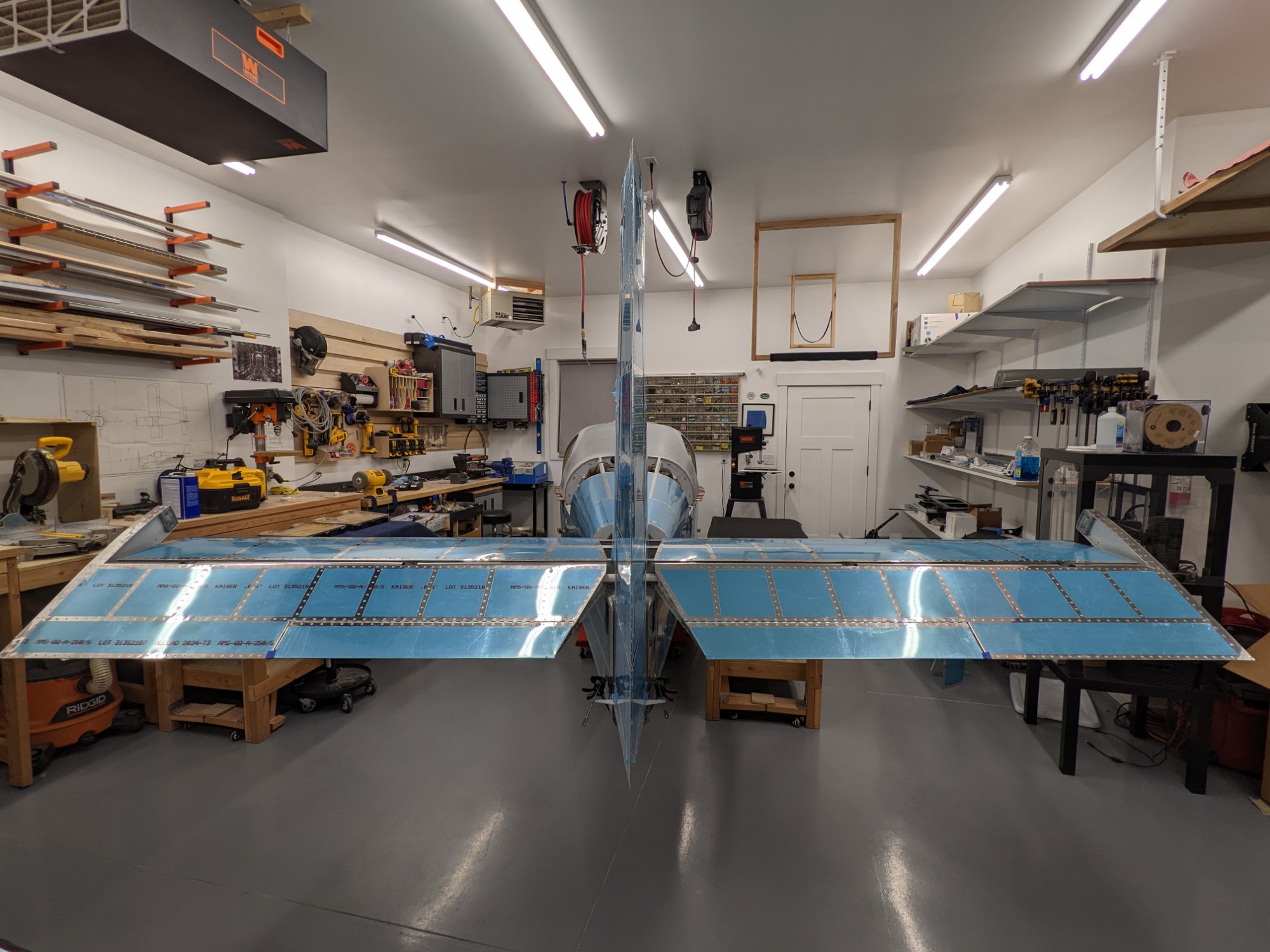
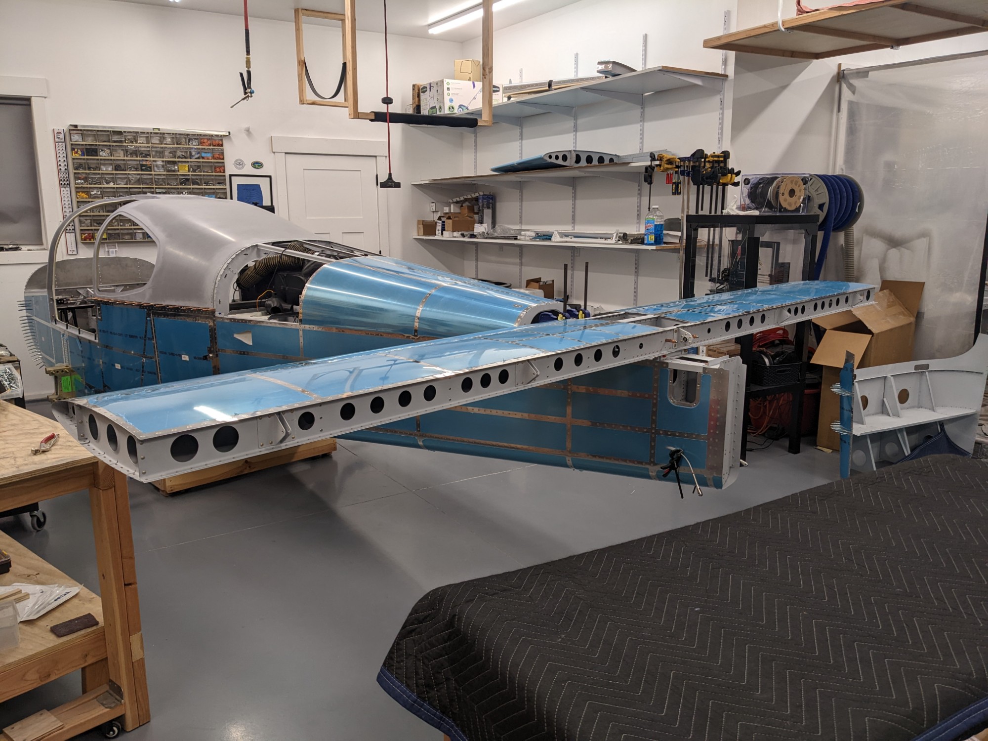
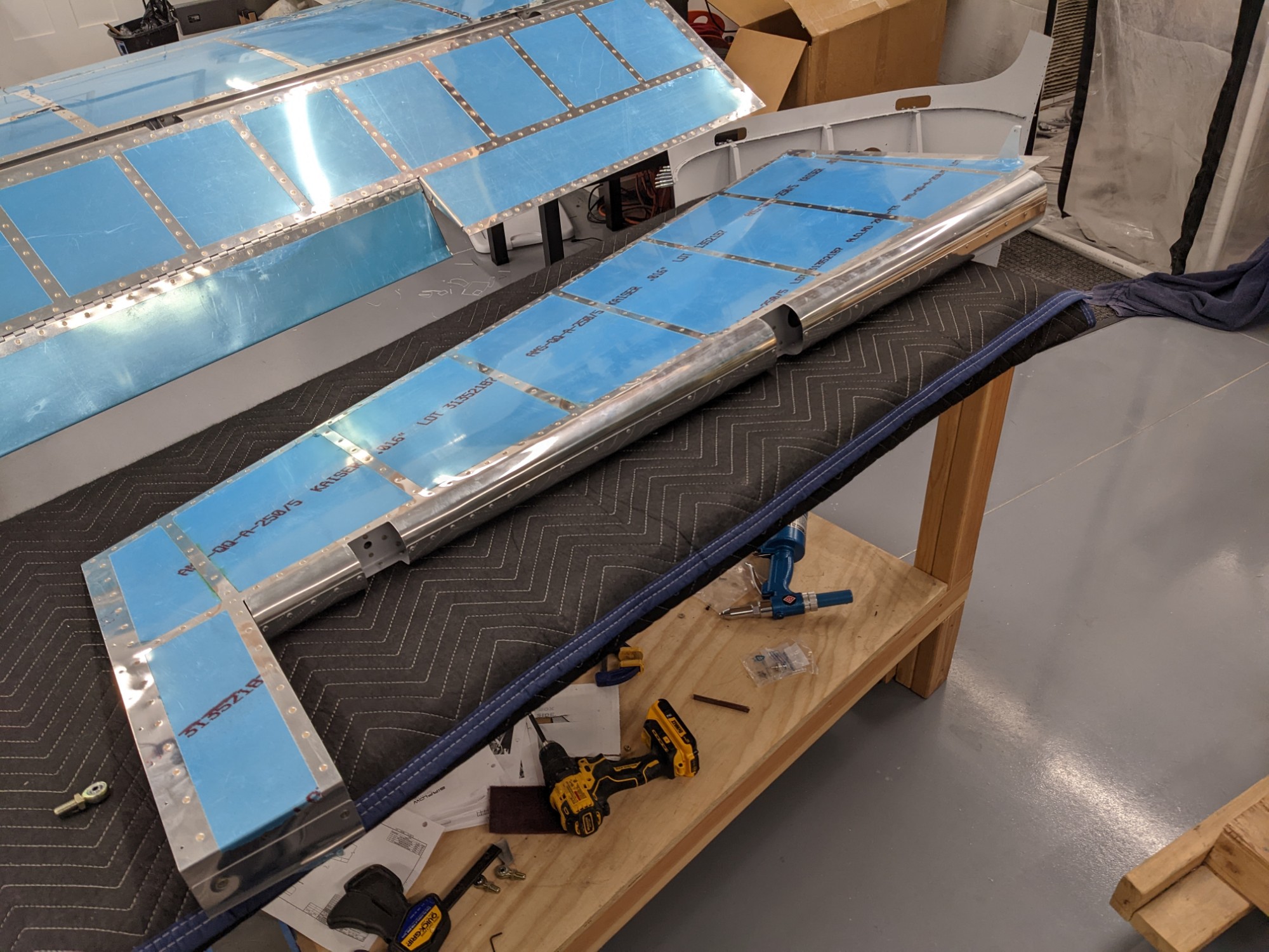
I’m still amazed by how perfectly all the parts are going together. Everything aligns well with minimal adjustments needed. All control surfaces move smoothly with no rubbing or binding.
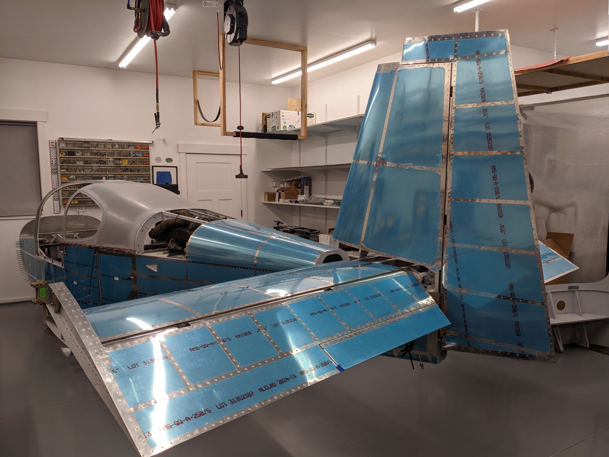
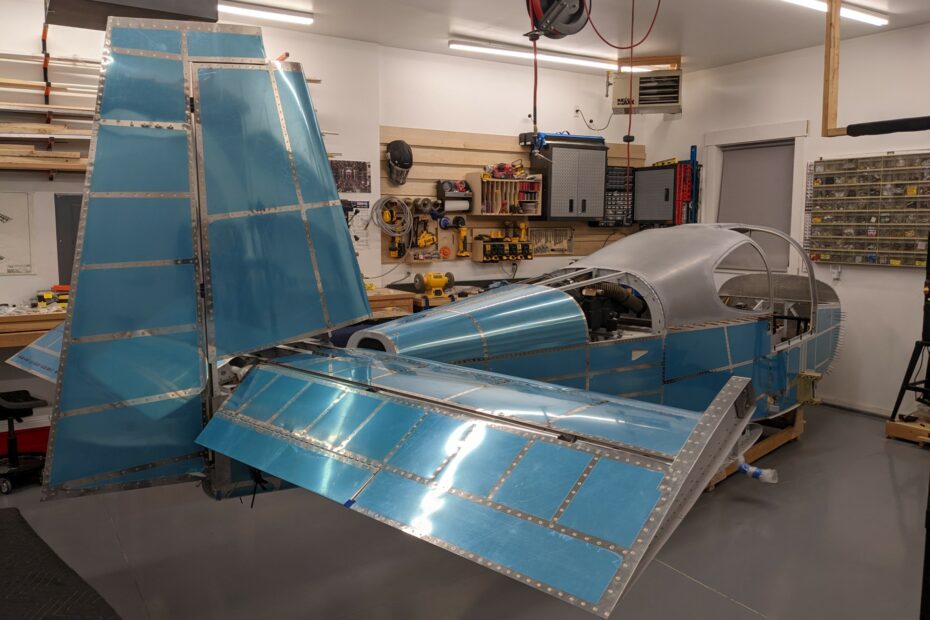
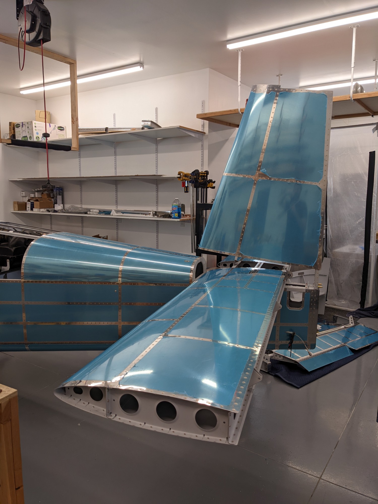
Starting to look like an airplane!