
I am installing an Airflow Systems ASAC-5000 air conditioning system in the airplane. This log entry describes work that has been completed over several work sessions and documents the installation of the A/C evaporator and my solution for switching the overhead console between conditioned air and outside air.
NACA Vent Scoops
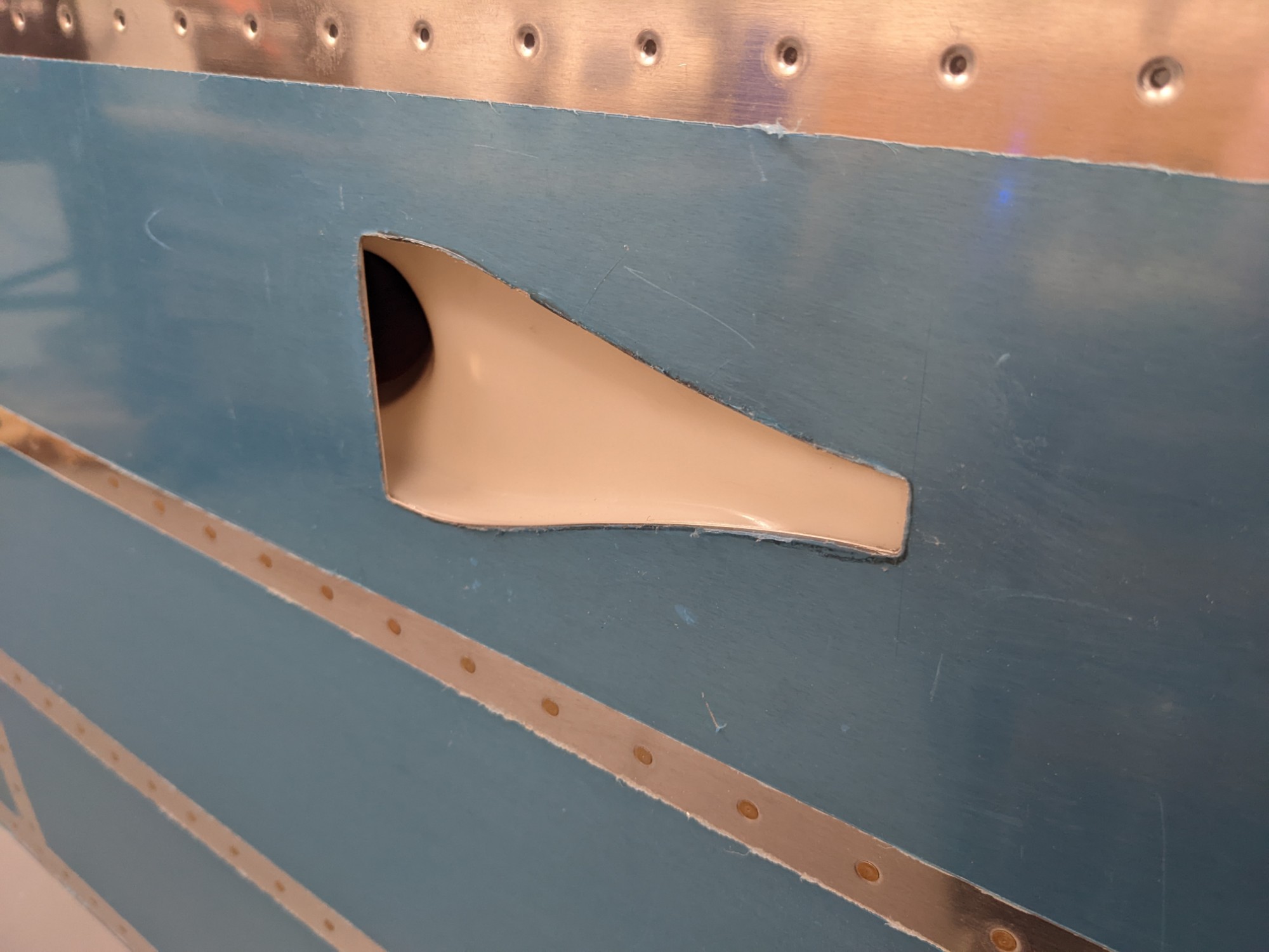
I had previously cut holes for rear NACA vents and it was time to get the scoops installed. I decided to bond these with the same 3M 2216 Epoxy Adhesive that I had used for the static ports.
I removed the primer and scuffed the bonding surfaces.
I mixed up some the epoxy and clamped the ports into place overnight.
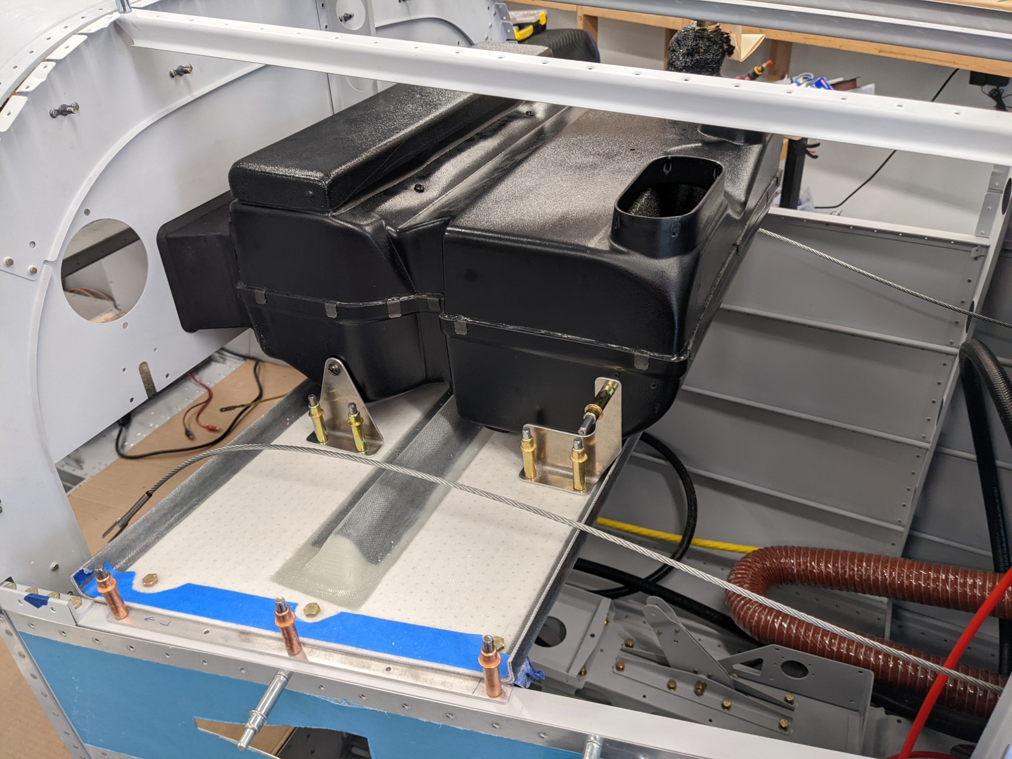
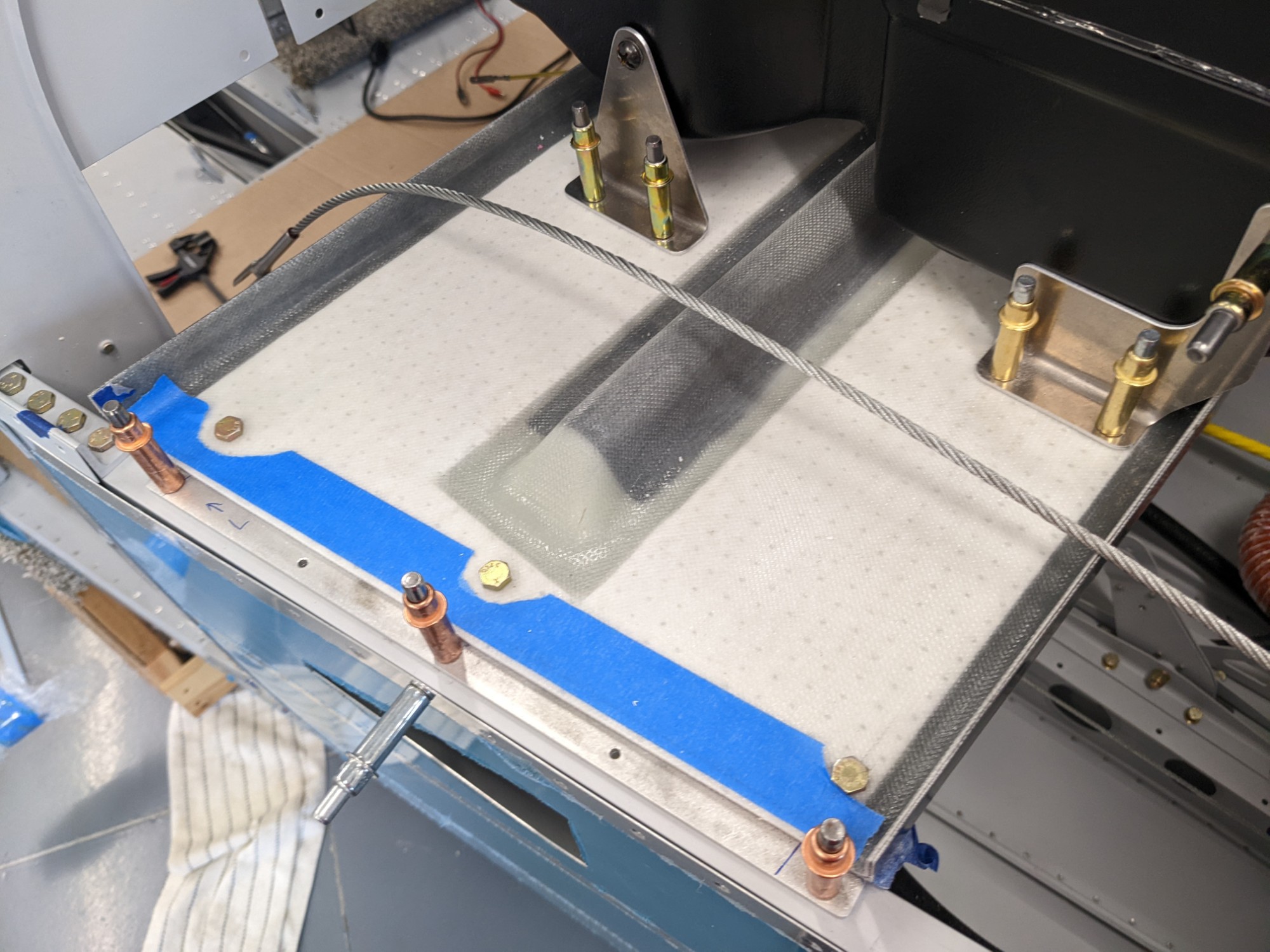
Evaporator Shelf
I chose to mount the aluminum support bars on top of the longerons (I noticed that some others have installed these on the underside of the longerons but I didn’t want to carry the weight on the rivets in tension). I then determined the forward/aft position of the shelf and trimmed it to length. I clecoed the top skin into place prior to match drilling the shelf to the supports to ensure the horizontal distance between longerons wasn’t affected.
Note that I deliberately chose to install the shelf upside-down for a few different reasons:
- The molding and layup of the part created a slight crown in the downwards direction. Flipping the shelf orients this crown upwards where it is better suited to carry the load. It seems like this is a newer part (lighter than the previous?) as it looks different than the Airflow Systems shelves that I have seen on other build logs.
- I did a few tests and found the shelf to be slightly more resistant to deflection in this orientation.
- I’m installing brackets for a carbon-fiber wrapped oxygen bottle on the underside of the shelf. Having a flat surface on the bottom simplifies this.
- There were no clearance issues with the bottom of the evaporator in either orientation.
The positioning of the evaporator on the shelf was a matter of aligning it with the holes in the aft bulkhead. I then match-drilled the holes into the shelf and match drilled the rear brackets into the evaporator unit.
I attached the shoulder harness cables to ensure I would have clearance from the other items that would attach to the shelf (like the receiver dryer).
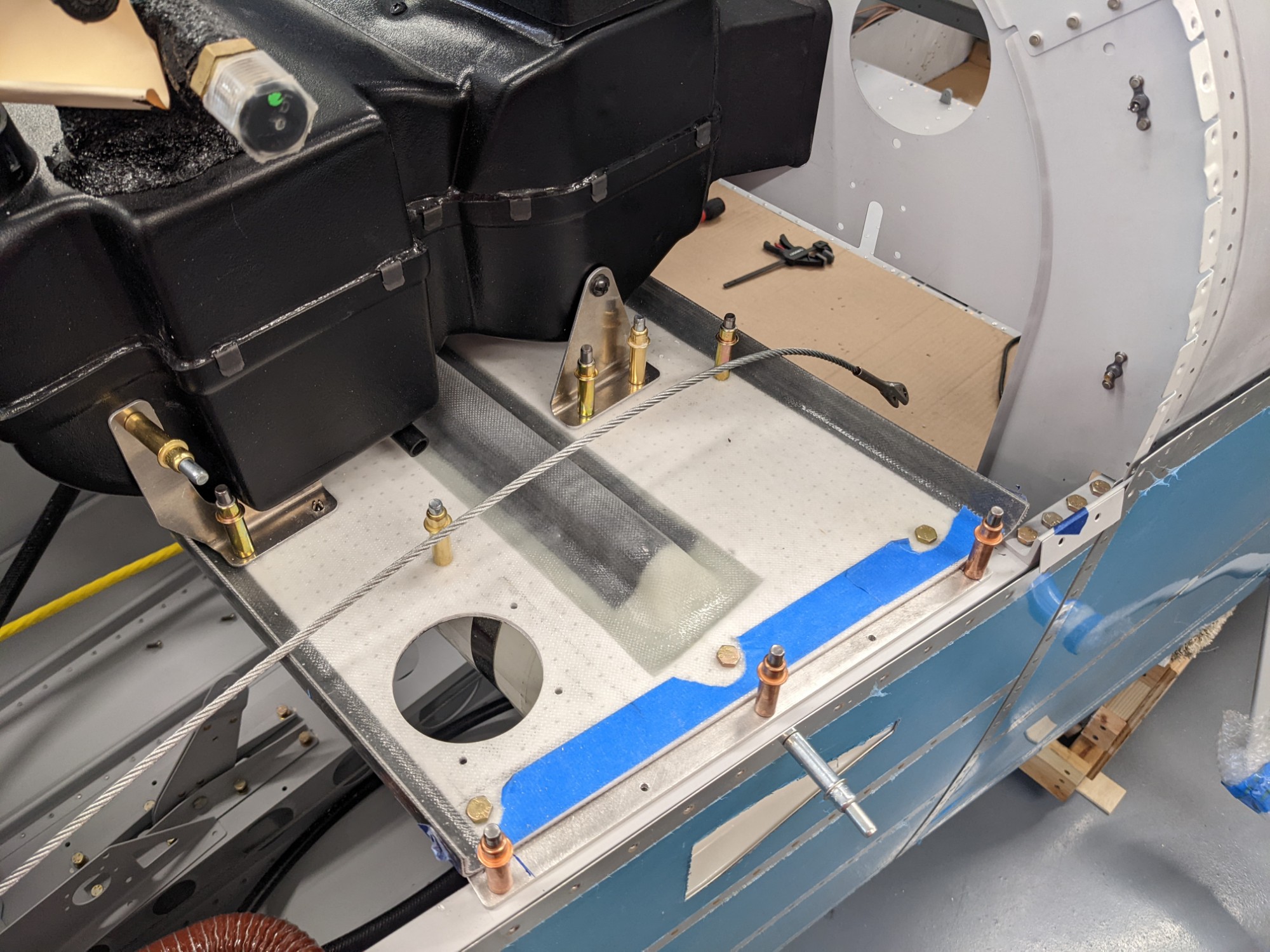
I chose to mount the receiver dryer on the co-pilot side of the shelf to avoid having hoses span the shelf laterally. I had also deliberately chosen to route the hoses down the tunnel and to have them exit underneath the rear of the co-pilot side of the baggage floor. This keeps the pilot side access to the tailcone as open as possible for the inevitable maintenance situations in which I will have to climb into the tailcone.
Bill from Airflow indicated that the #6 high-pressure hose needs at least 10-12 inches of hose between the evaporator and receiver dryer (for pressure expansion) so I plan to add a loop aft of the evaporator to accommodate this. I mounted the receiver dryer to the right of the shoulder harness cable to give it plenty of clearance.
Air Distribution Manifold
The manifold that comes with the Airflow Systems A/C is designed to deliver conditioned air to the openings in the aft bulkhead and into an overhead console. The primary airflow from the A/C is intended to flow upwards and forwards along the ceiling of the cabin towards the front windshield.
I also wanted the option to use outside air to pressurize the overhead console when conditioned air isn’t needed. I considered using the Aerosport NACA Vent Valve Kit but I didn’t see a clean way to integrate this with the Airflow Systems manifold.
I ended up designing a custom manifold with the following design goals:
- Allow conditioned air from the evaporator to flow to the rear bulkhead flood vents and pressurize the overhead console.
- Allow outside air from the NACA ducts to pressurize the overhead console but allow this air to be turned on/off via a servo-operated valve.
- When outside air is on, don’t allow that outside air to flow to the rear bulkhead flood vents or backward through the evaporator.
- Allow the servo to be serviceable without having to remove the manifold or the evaporator.
- Allow it to be printable on an FDM 3D printer (I use a Prusa i3 MK3S+).
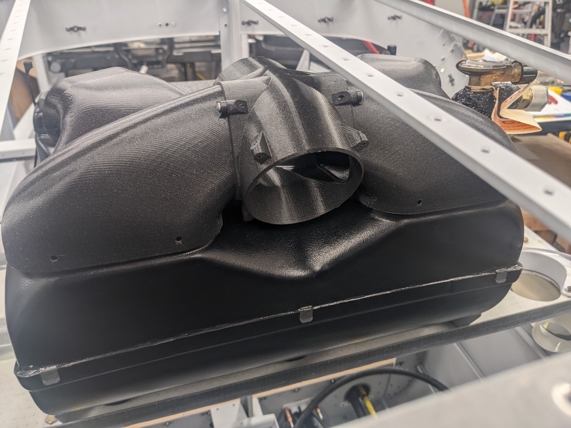
I designed the manifold in OnShape. The assembly is printed in 4 primary parts for printability.
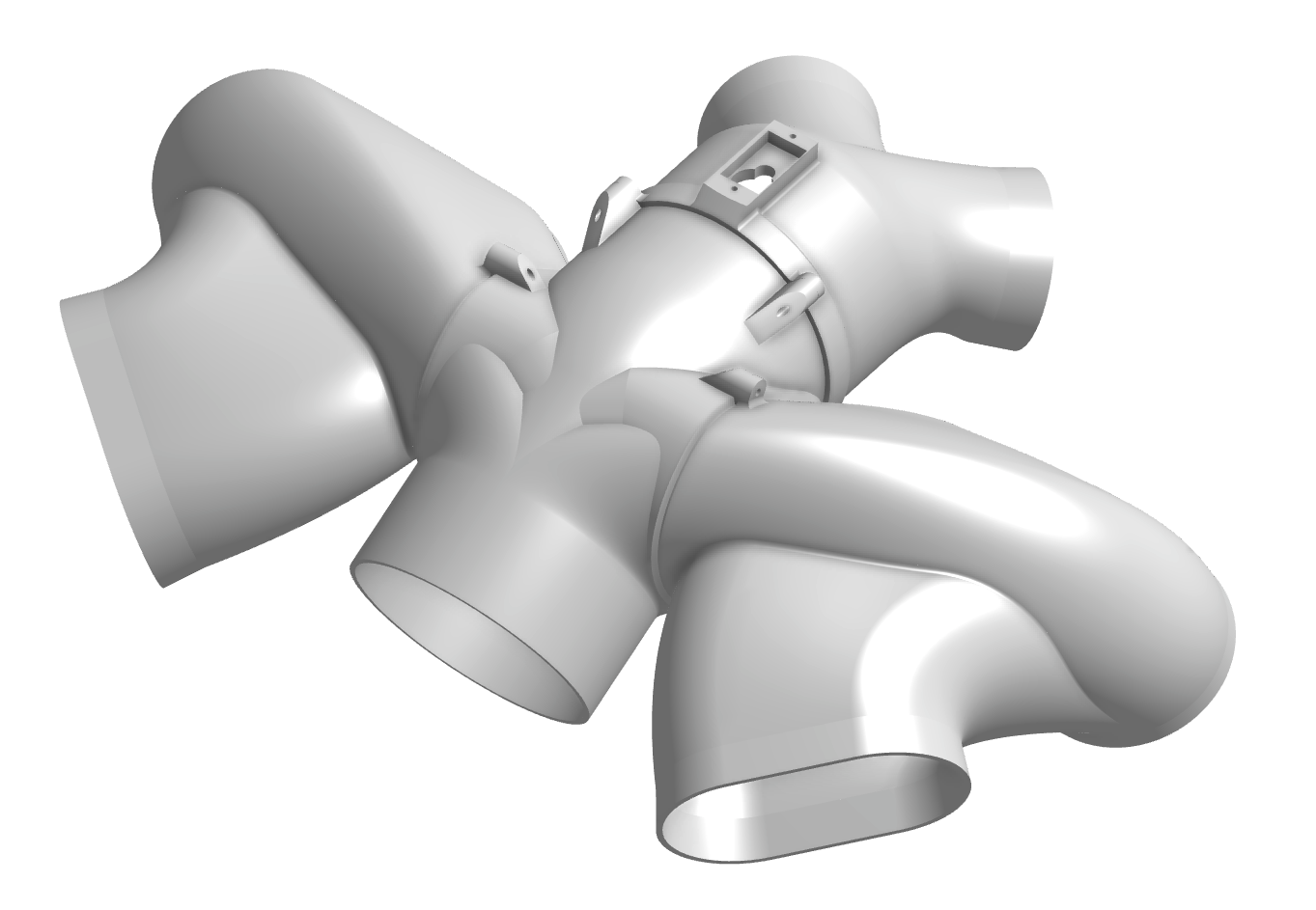
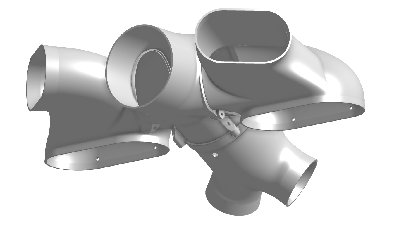
When assembled, the main body of the manifold (the center section and inlets from the evaporator) are permanently attached while the aft portion remains removable for maintenance.
Backdraft dampers are installed at the joint between the center section and the inlet to restrict reverse airflow to the bulkhead flood vents and to the evaporator outlets.
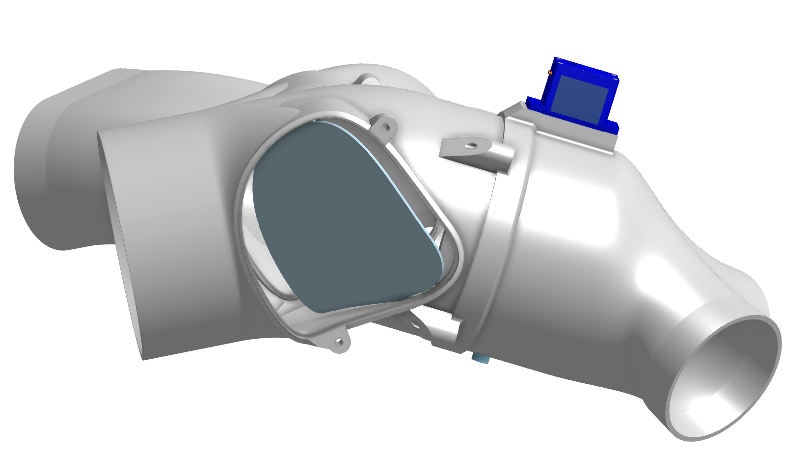
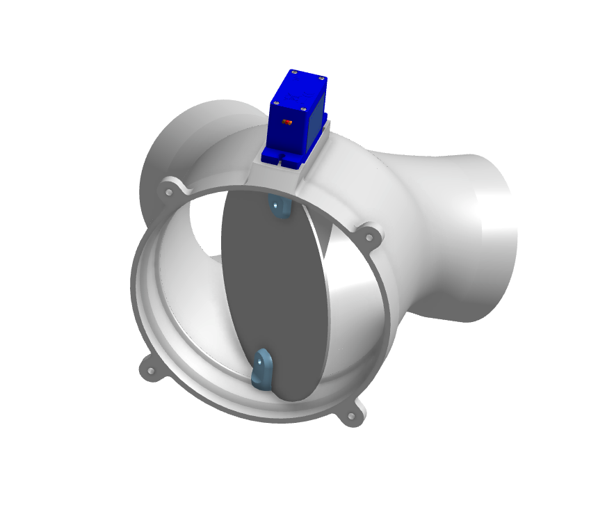
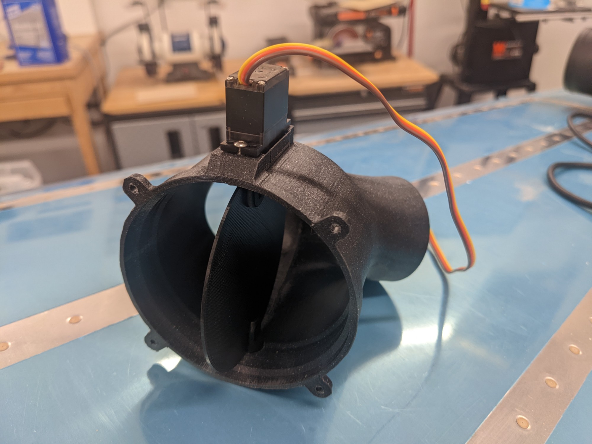
The valve portion of the manifold houses a metal-geared 90° high torque mini servo that has a direct drive to an aluminum butterfly valve. A split flange around the wall of the valve helps to seal against outside air when the valve is closed. The valve portion was designed to be removable so that the servo can be easily replaced and so that the action of the valve can be easily inspected and/or adjusted. I am driving the servo with an ESP32.
The assembly mounts on top of the evaporator outlets with screws at the rear. The manifold was designed to allow it to be removable when the top skin is riveted in place (it is low enough in profile that it lifts forward and can be removed down the side of the evaporator).
The valve section is then mounted to the rear of the manifold and attaches with 4 small screws. The flap in the picture is 3d printed for testing but the actual flap is made from aluminum for rigidity.
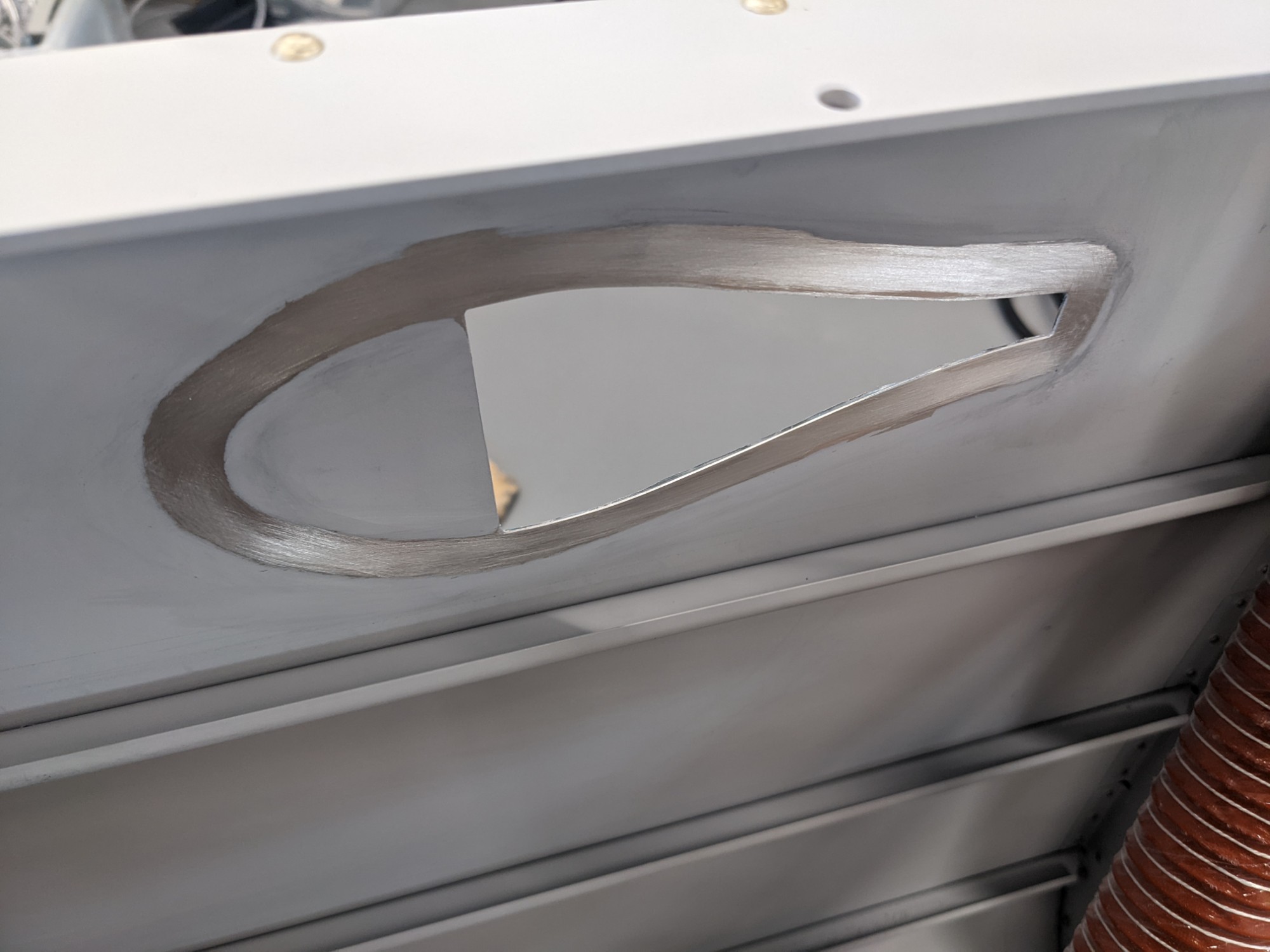
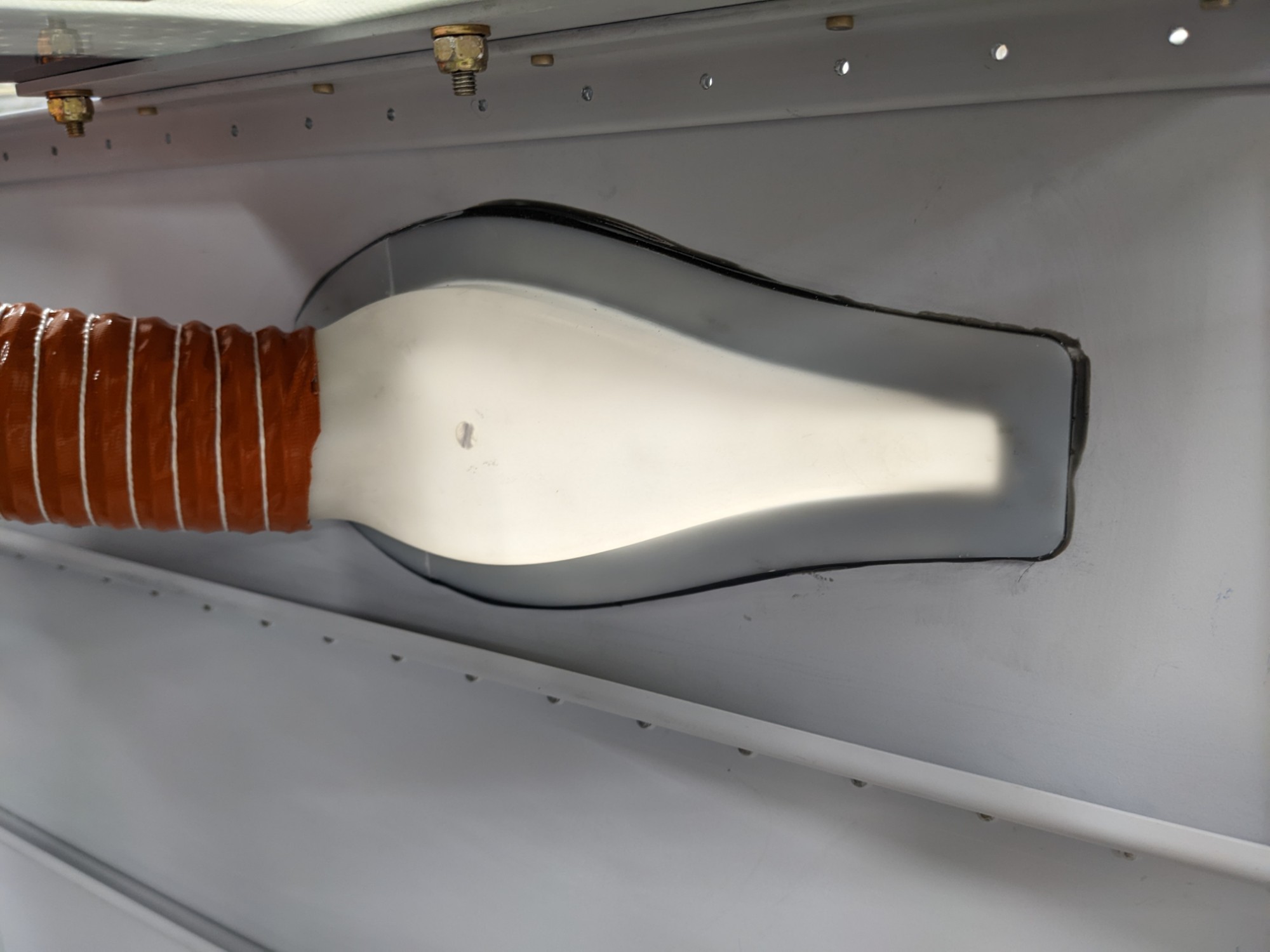
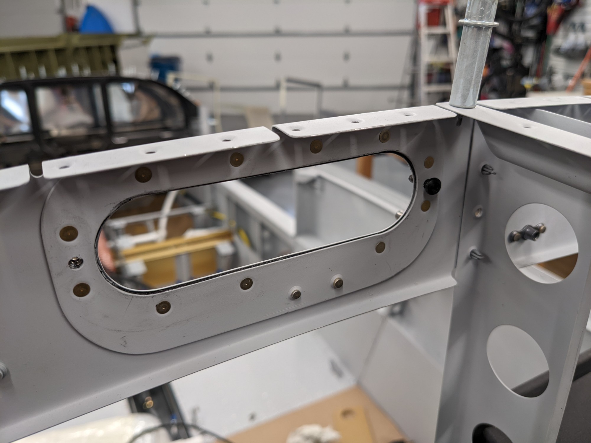
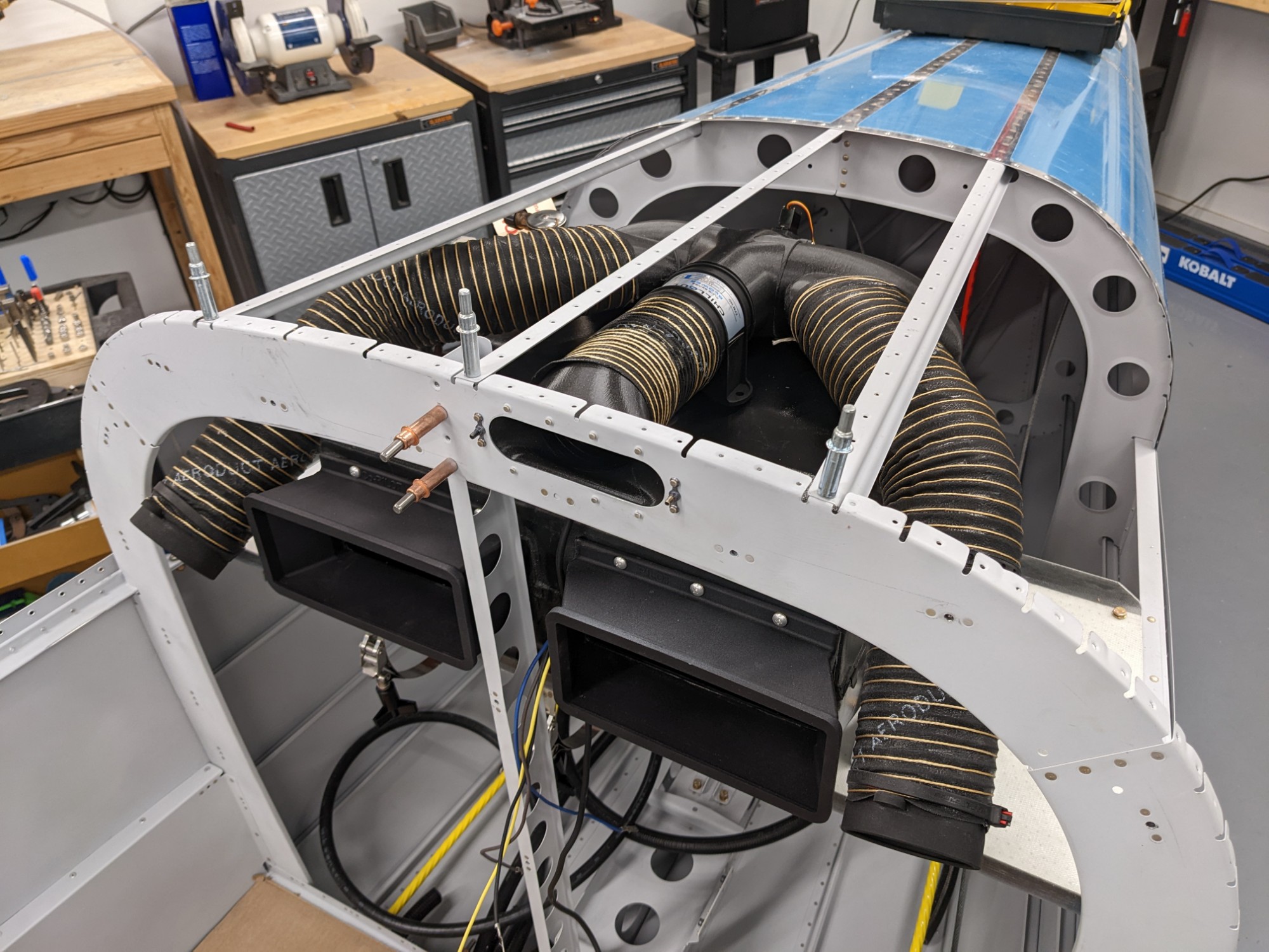
I additionally designed a duct to allow the air from the manifold to pressurize the overhead console. I chose to do this with one opening (instead of the two 2″ circular openings that would typically be used with the Aerosport NACA valve). I made a doubler to strengthen the bulkhead around the opening and I added nutplates on the forward side to allow the duct to be removable from the tailcone. I slotted the innermost hole in the duct flange to make it easier to attach after the top skin is riveted into place. I’ll seal the flange to the bulkhead with RTV during the final install.
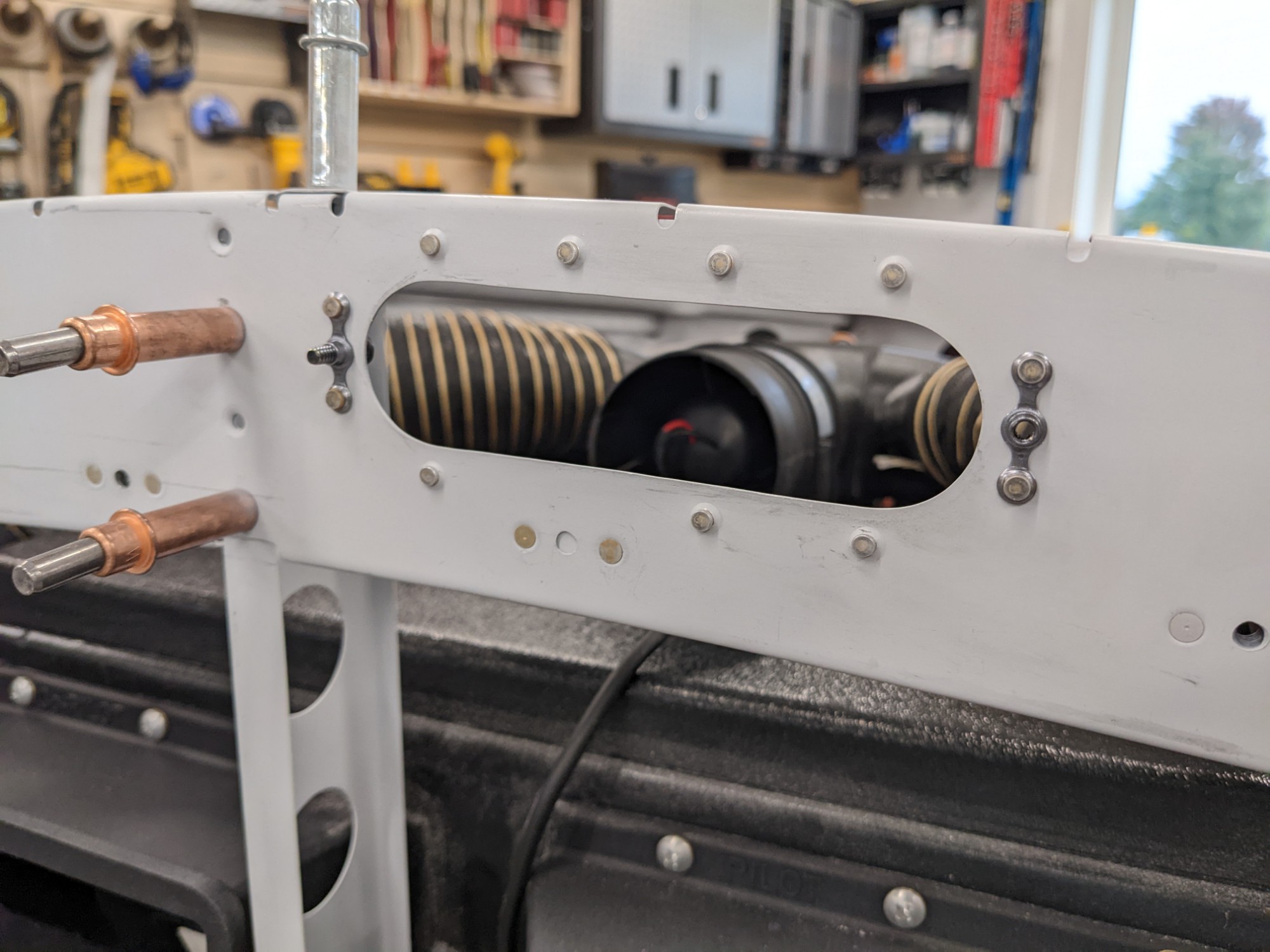
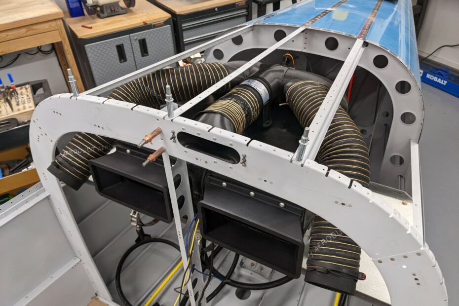
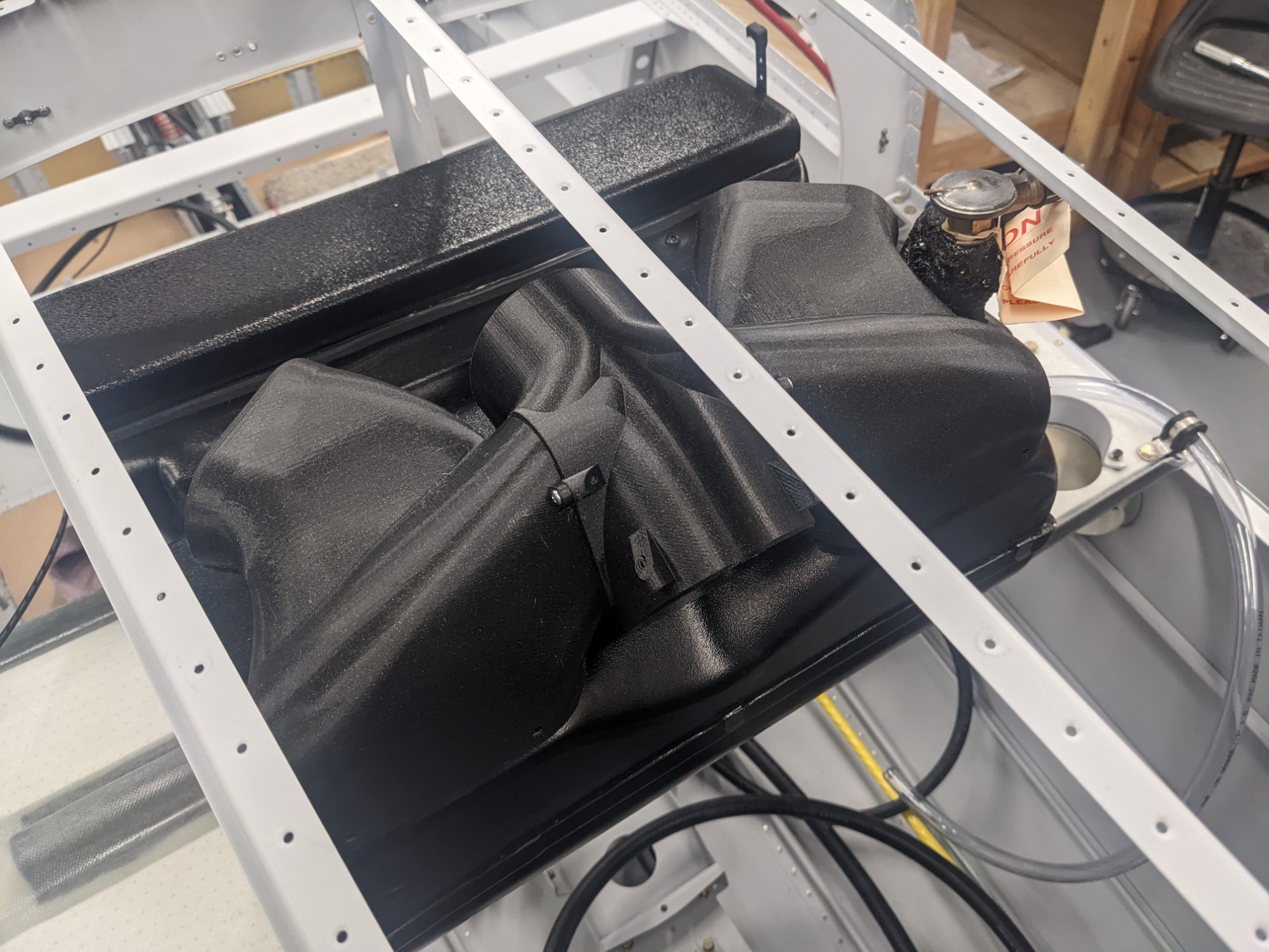
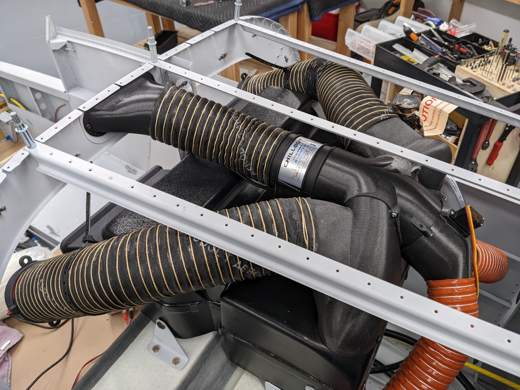
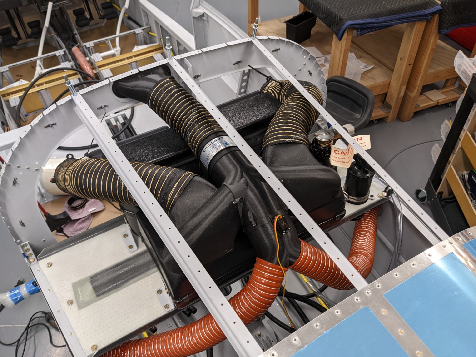
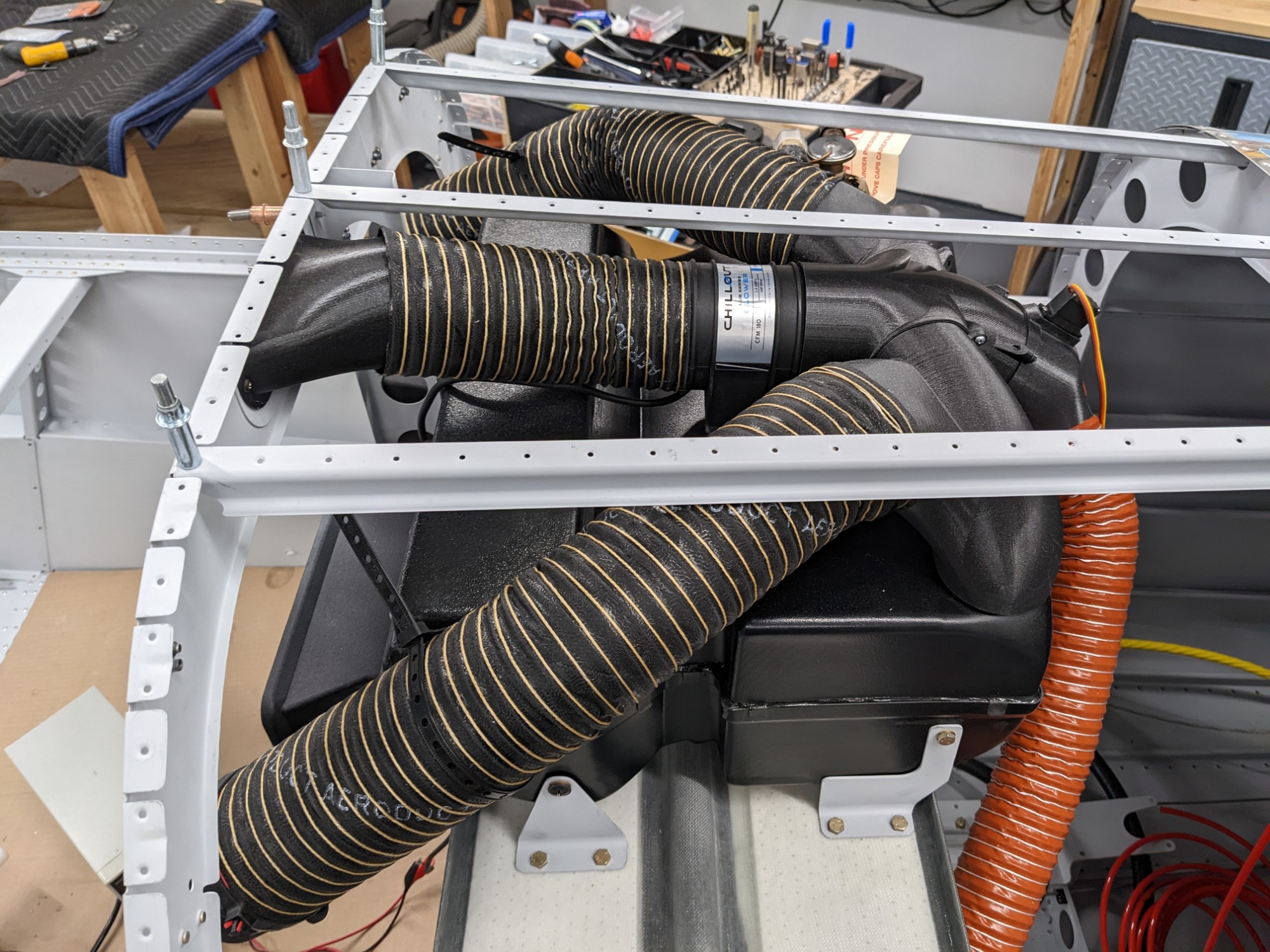
This is how everything looks when the hoses are fitted. I added a lightweight inline blower (as some others have done) to increase airflow to the overhead console. I’m not certain this is needed and it is easily removed later if not necessary.
I conducted some testing by powering up the evaporator blower and the inline blower. I used a shop vac to pressurize the lines from the NACA ports to simulate outside air. Everything worked as designed but I won’t know for sure until I have a flying airplane.