
The opportunity to build my engine at the Aero Sport Power was too good to pass up and I have been looking forward to doing this since I started building the airplane four years ago. I placed an engine deposit with Aero Sport in mid-2022. Post-COVID supply chain issues resulted in significant delays but this has worked out with the pace of my build.
I was able to get on the build school calendar in early July 2024 and drove up to Kamloops, BC to build the engine. My brother flew up to join me for the build. The build school requires three days – two days to build the engine and a final day to test it.
This log entry doesn’t detail every step in the assembly but it covers most of the key steps. My brother did a great job at capturing the build with photos and video and I have posted the majority of that content here. This mostly serves as a log for me but I’m hoping that others find this useful.
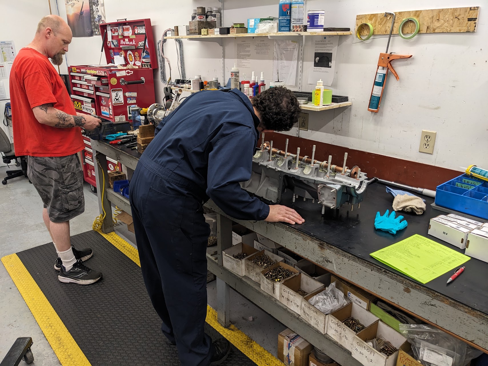
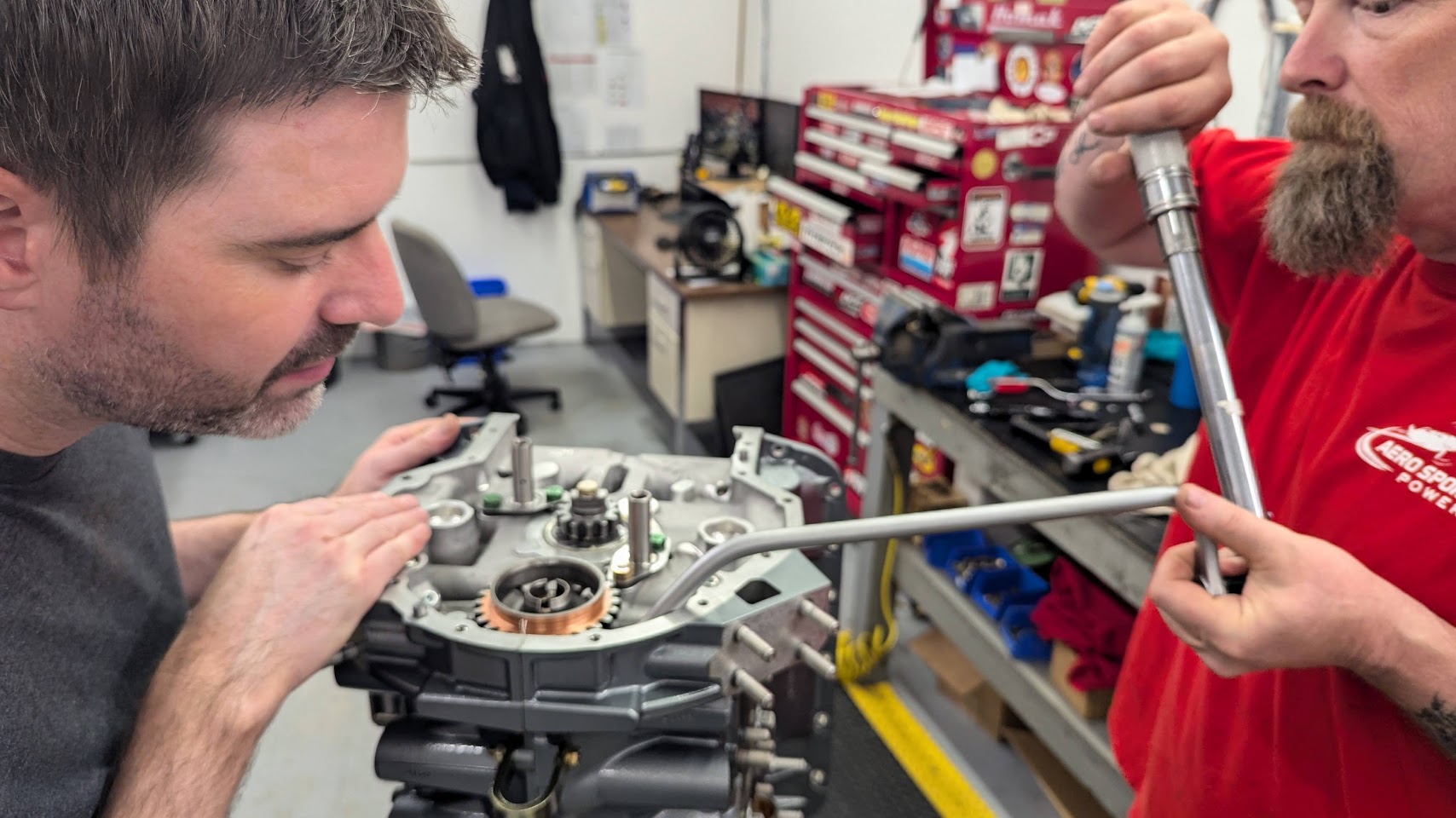
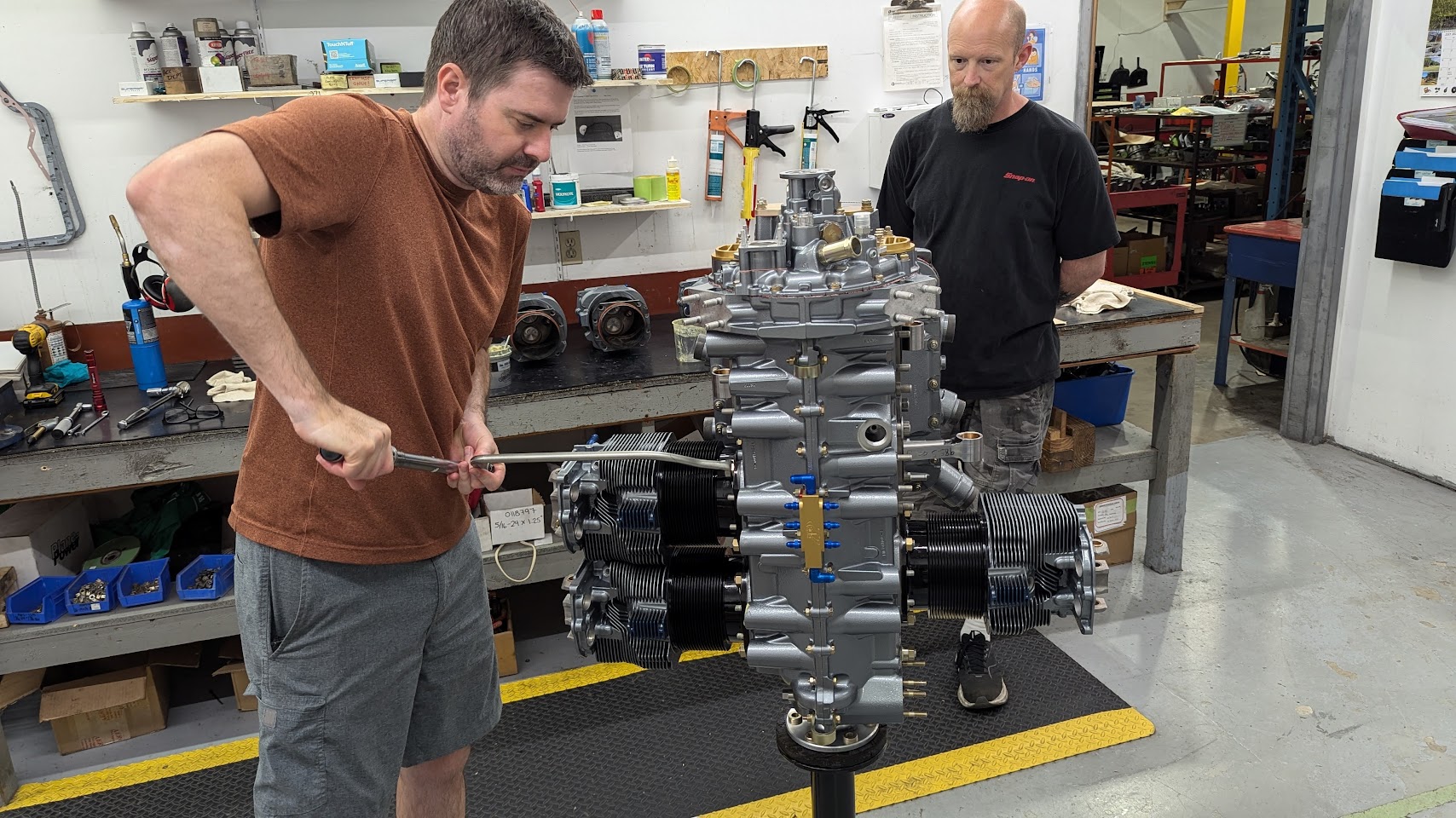
Our experience at Aero Sport was excellent. Darren Jones was on top of everything throughout the entire process from the initial quote. We built our engine with Terry who has built over 200 engines. It is amazing how quickly the engine comes together when all of the parts are laid out and guided instruction is provided for every step.
I have broken out the content by day with direct links to jump to each day:
- Day 1 (engine case, accessory housing, oil sump, etc.)
- Day 2 (cylinders, ignition, test stand prep, etc.)
- Day 3 (engine testing)
Day 1
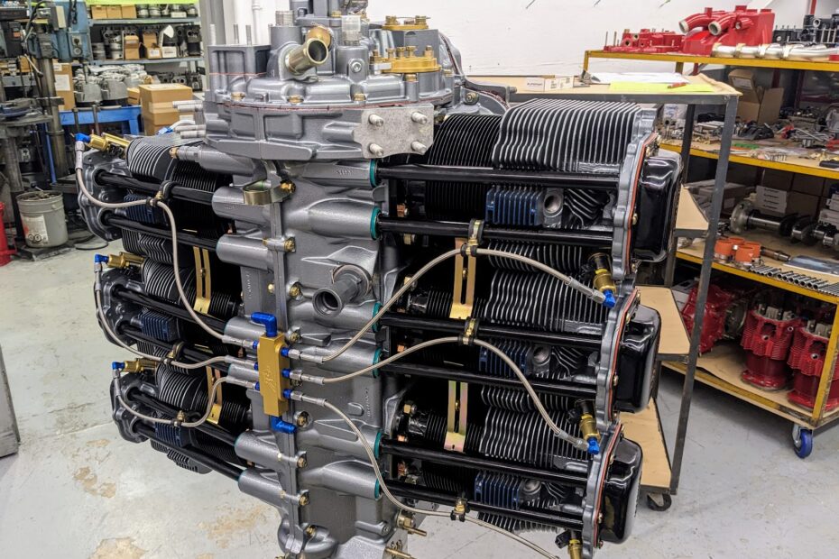
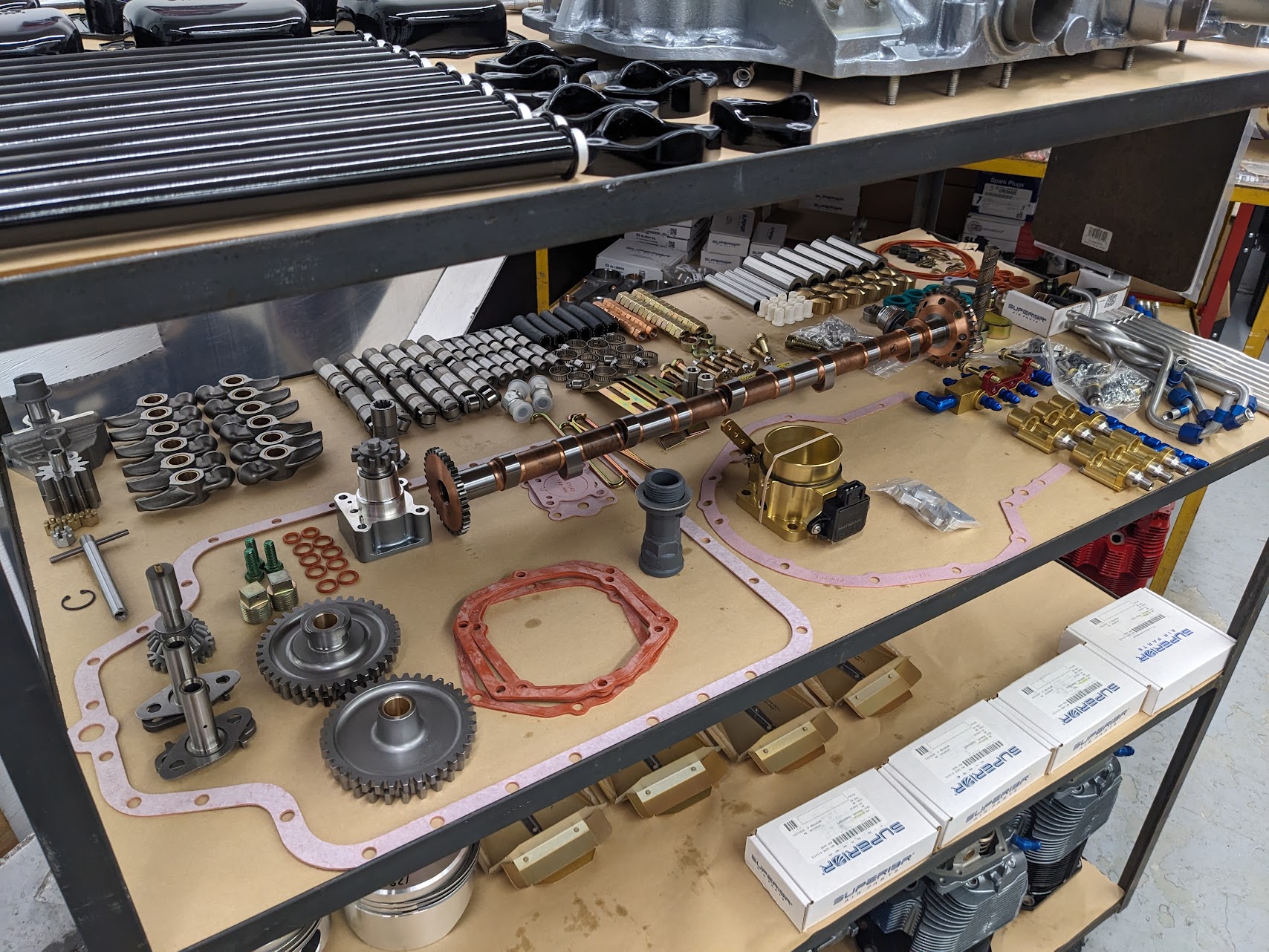
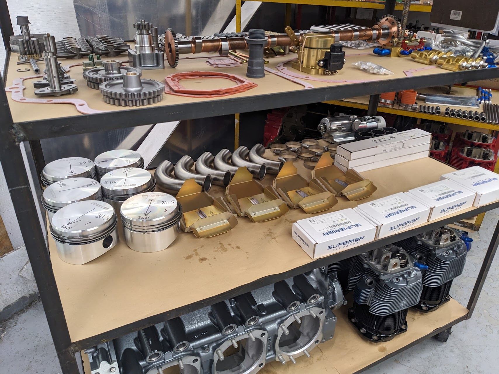
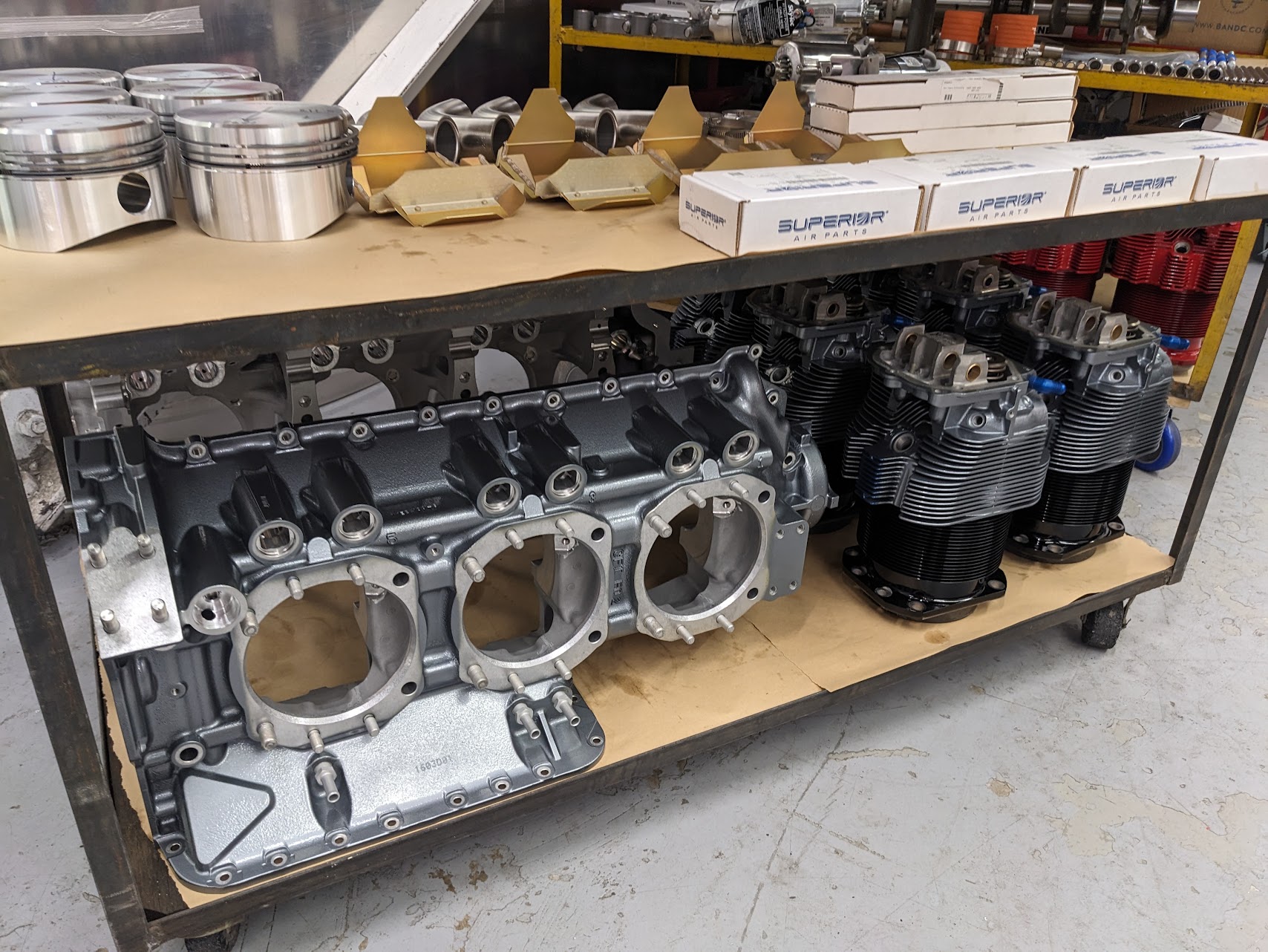
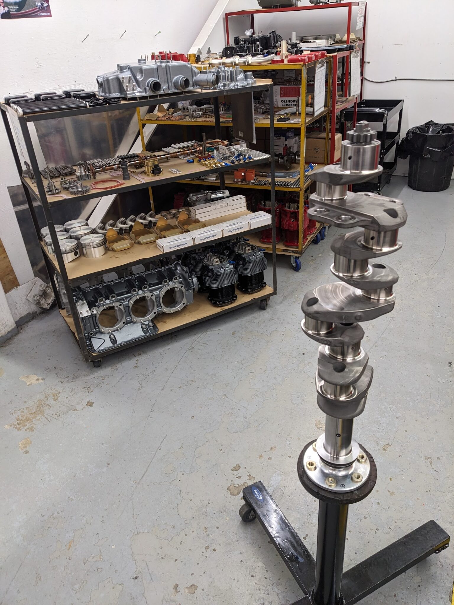
When we arrived on Monday the parts were laid out on shelves with the crankshaft mounted vertically on a rolling stand. About a day’s worth of prep is already complete with parts balanced, checked for tolerances, parts marked, cylinders ported and polished, etc. I shipped my Airflow Systems A/C dual-pulley ring gear in advance and Aero Sport had already installed the magnets for the SDS hall effect sensors.
We arrived just before 7:30 am and were given a tour of the space (facilities, lunch room, safety equipment, etc.). We started the build just before 8:00 am. Two 15-minute breaks and a 30-minute lunch break are taken during the day.
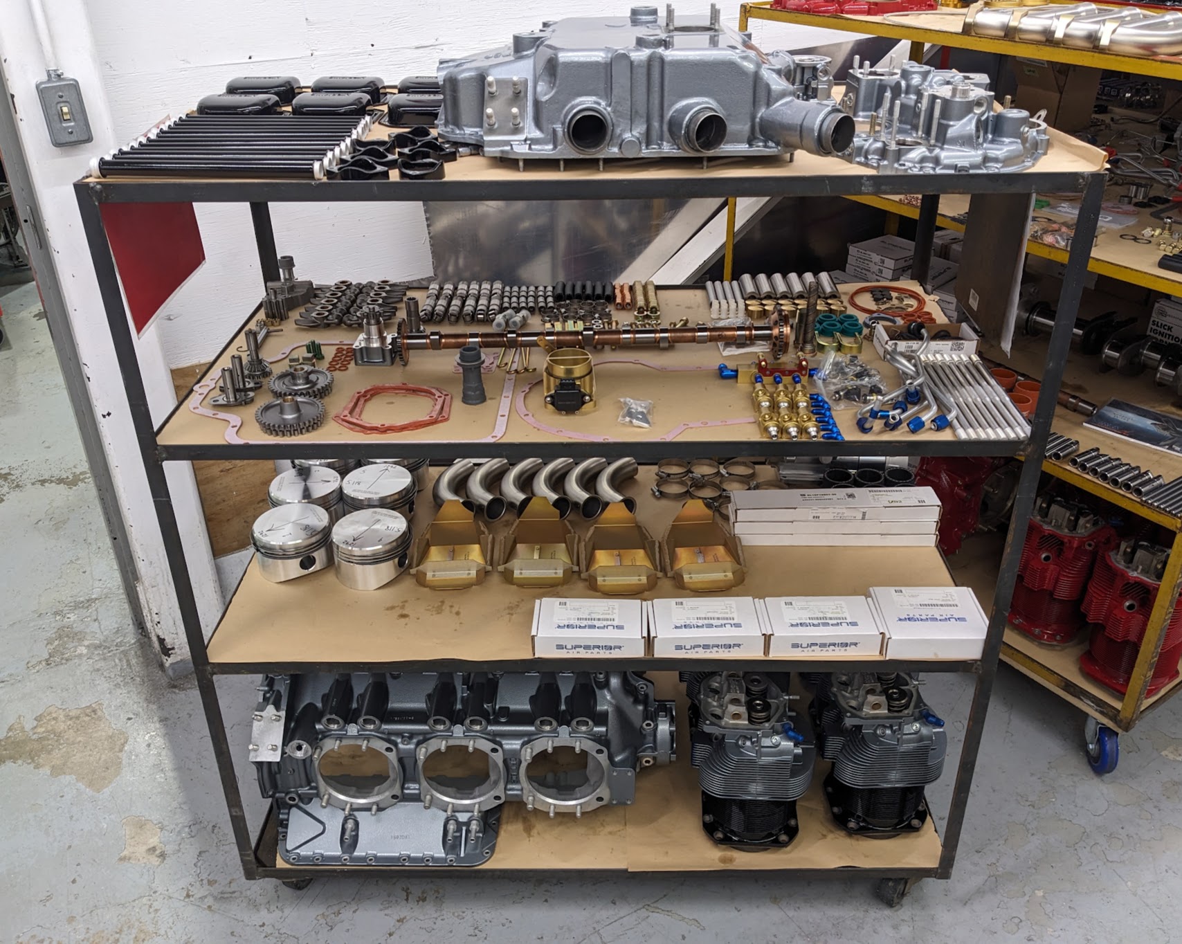
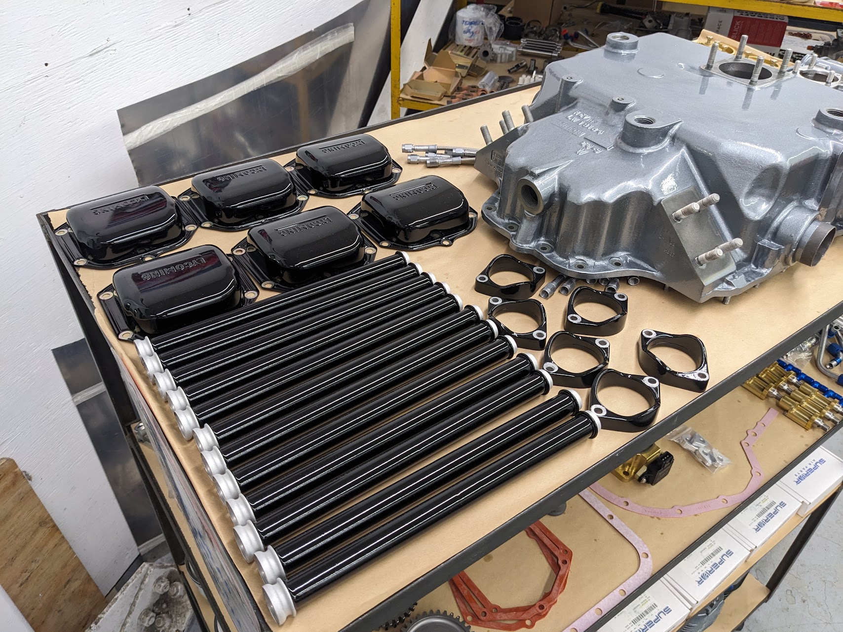
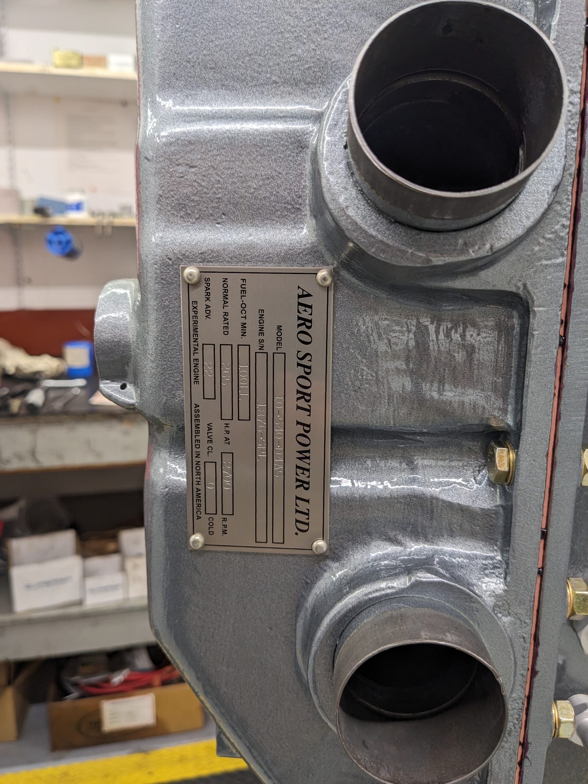
I chose a black/metallic grey color scheme and the parts were beautifully painted and ready for assembly when we arrived on Monday morning.
All parts were new except for the magnesium oil sump (I opted to stick with a traditional vertical induction sump instead of going to cold air induction). Aero Sport hasn’t been able to get new sumps from Lycoming so this sump was pulled from a used engine. I was given the choice to wait for a new sump but opted to proceed with a used sump as this is a non-mechanical part.
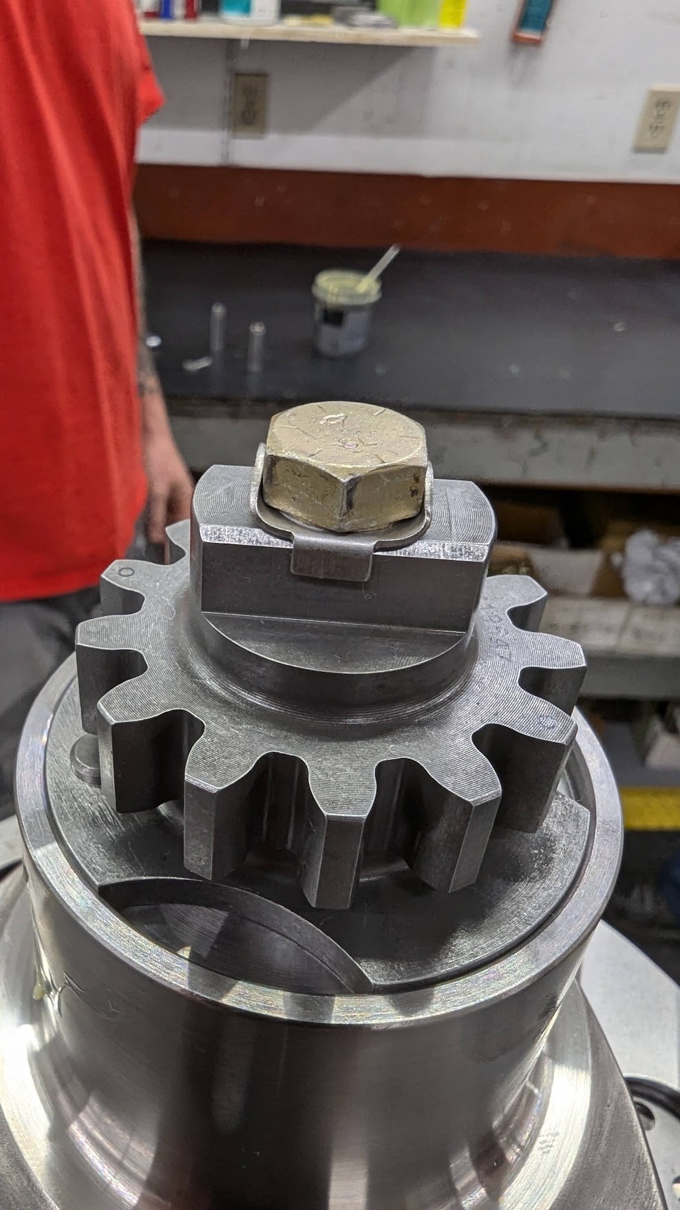
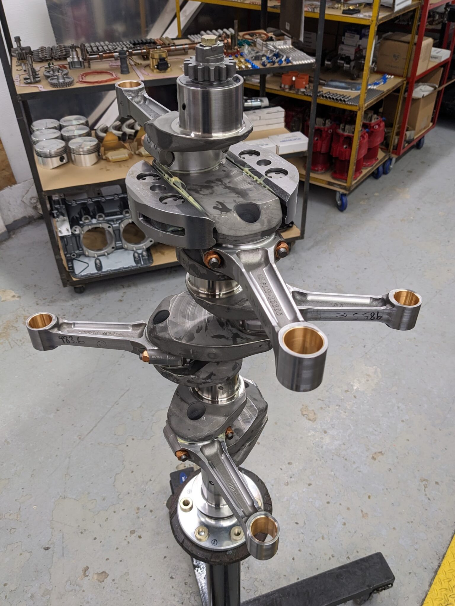
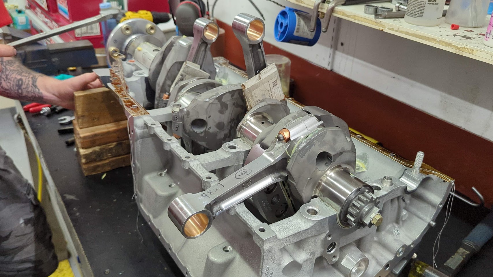
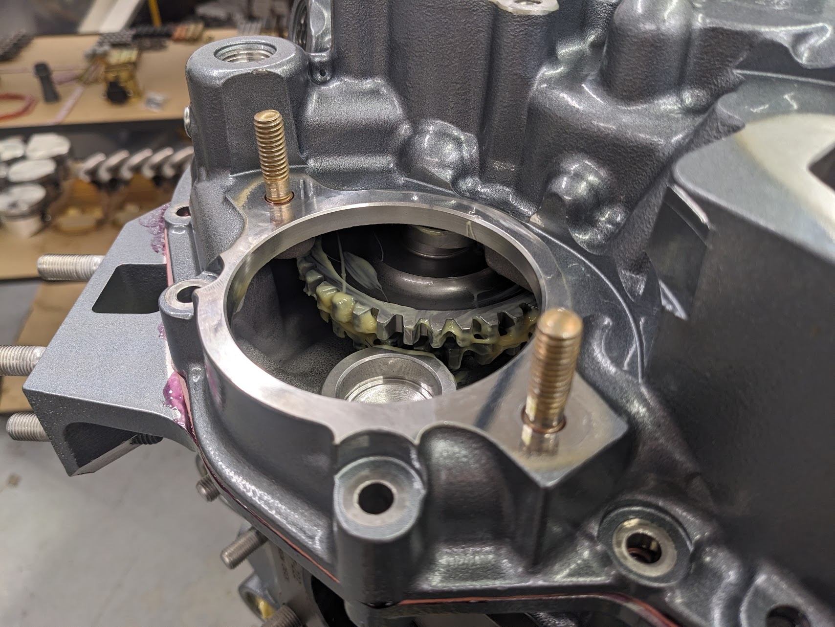
The build starts with the crankshaft mounted vertically to a rolling stand.
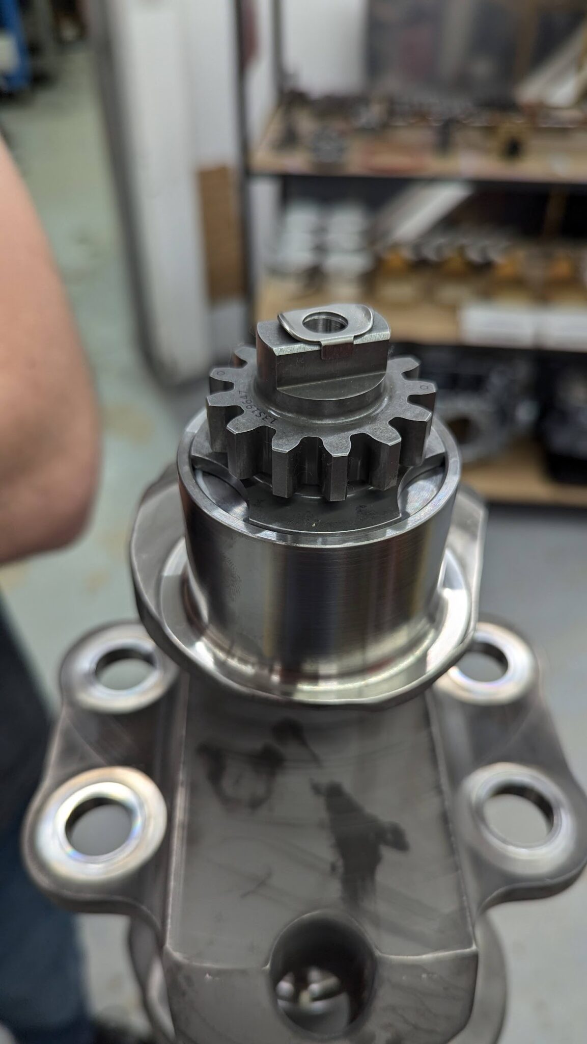
The crankshaft gear is the first part that is installed. This drives everything in the accessory housing.
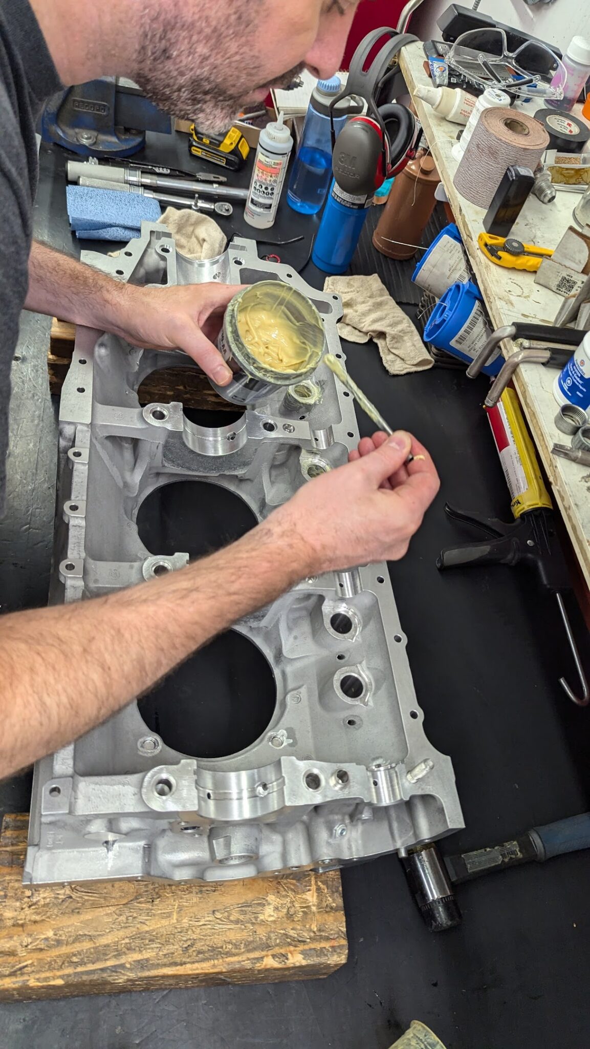
The connecting rods are then installed. Terry, our build technician, demonstrated the steps that were required then had us complete the steps for the remaining parts (multiples of 6 for a lot of parts). Grease is applied liberally to all contact surfaces for the first start.
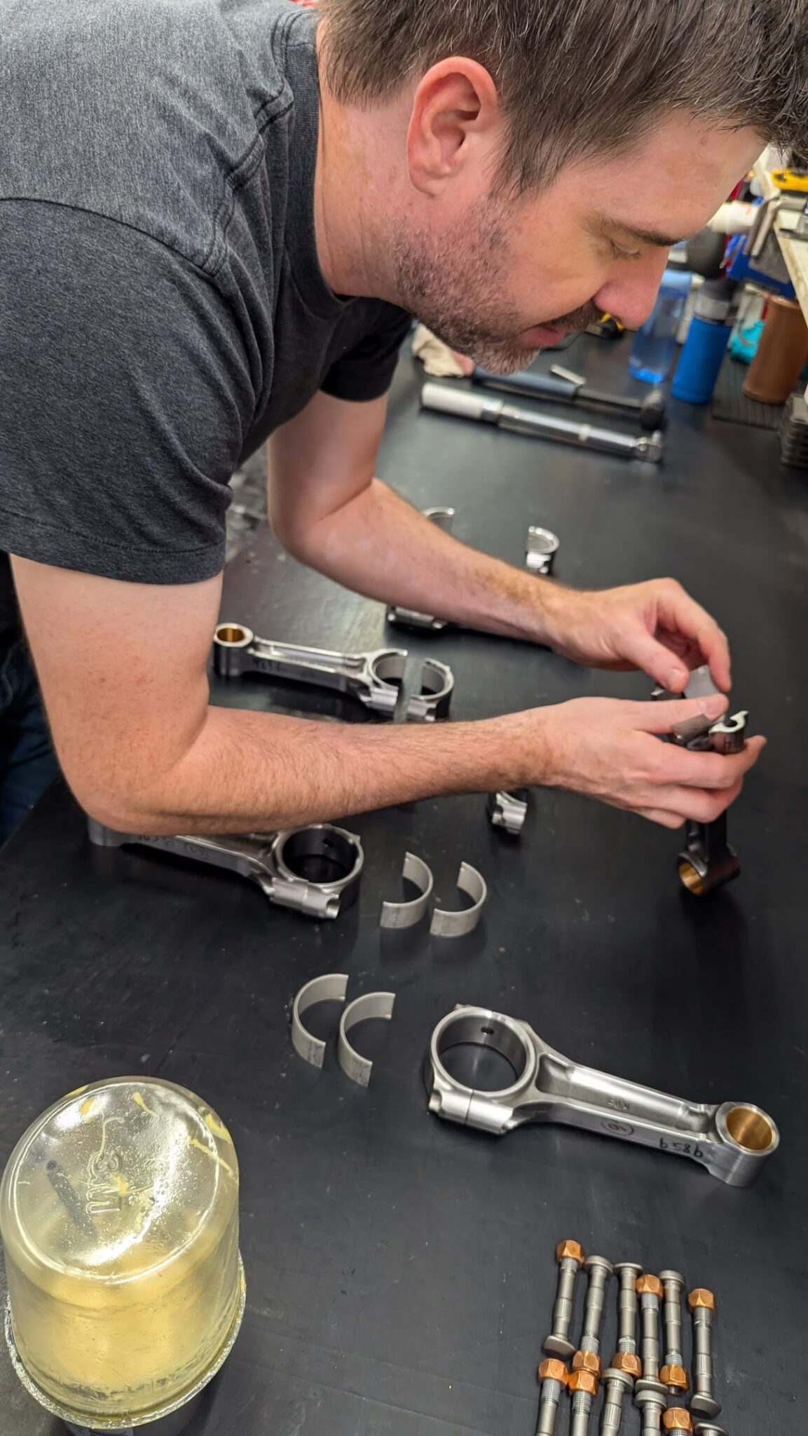
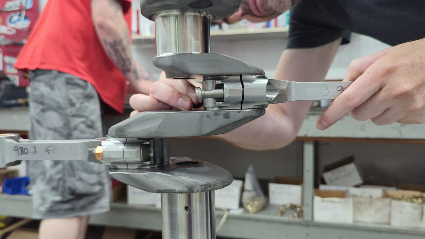
The IO-540 uses dynamic counterweights to suppress torsional vibration and the engine should be operated accordingly (smooth, steady throttle movements).
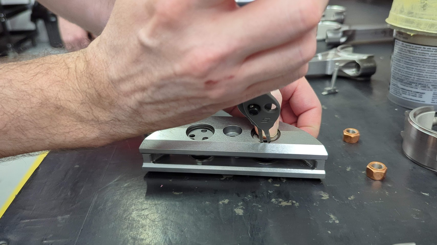
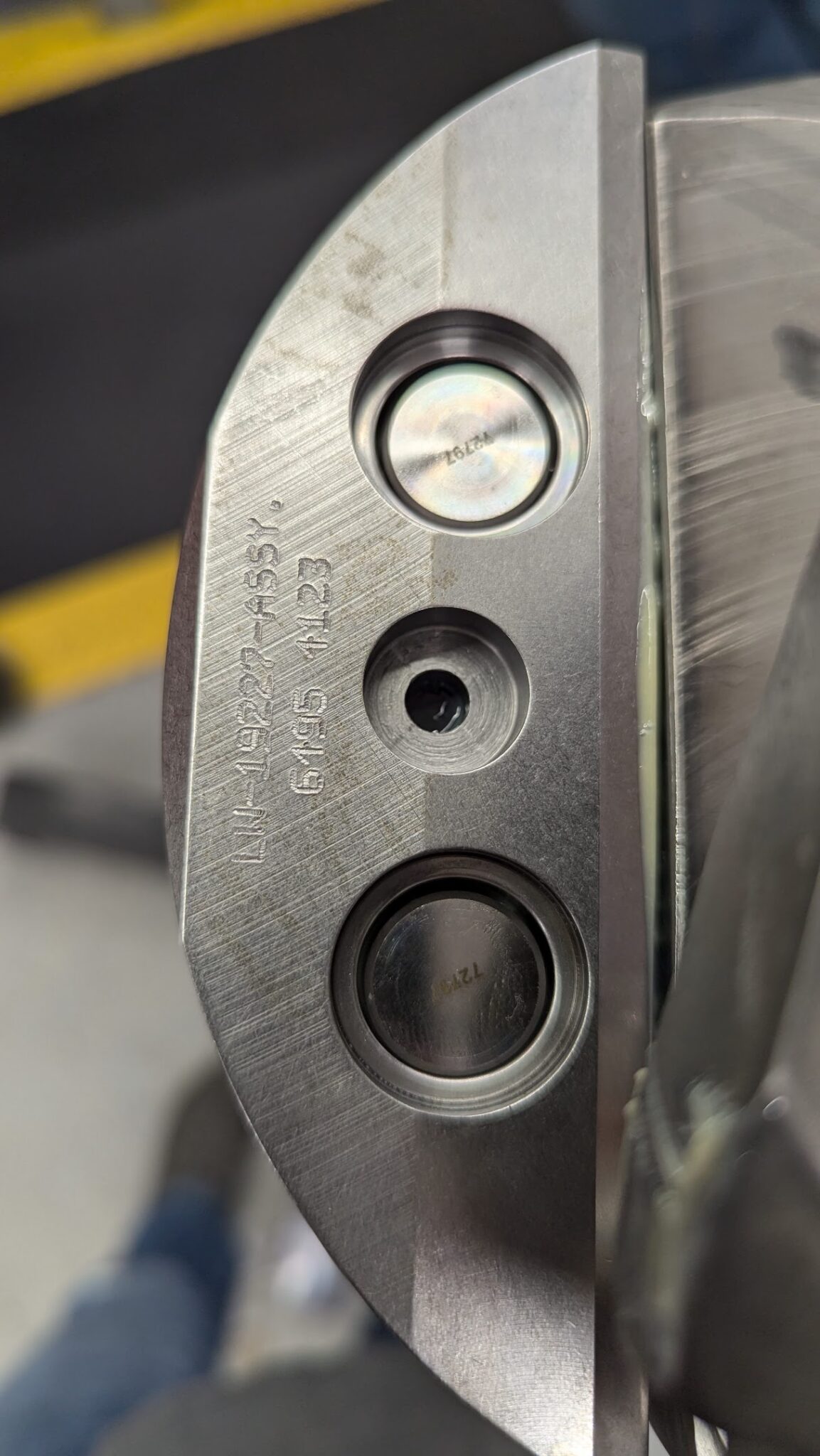
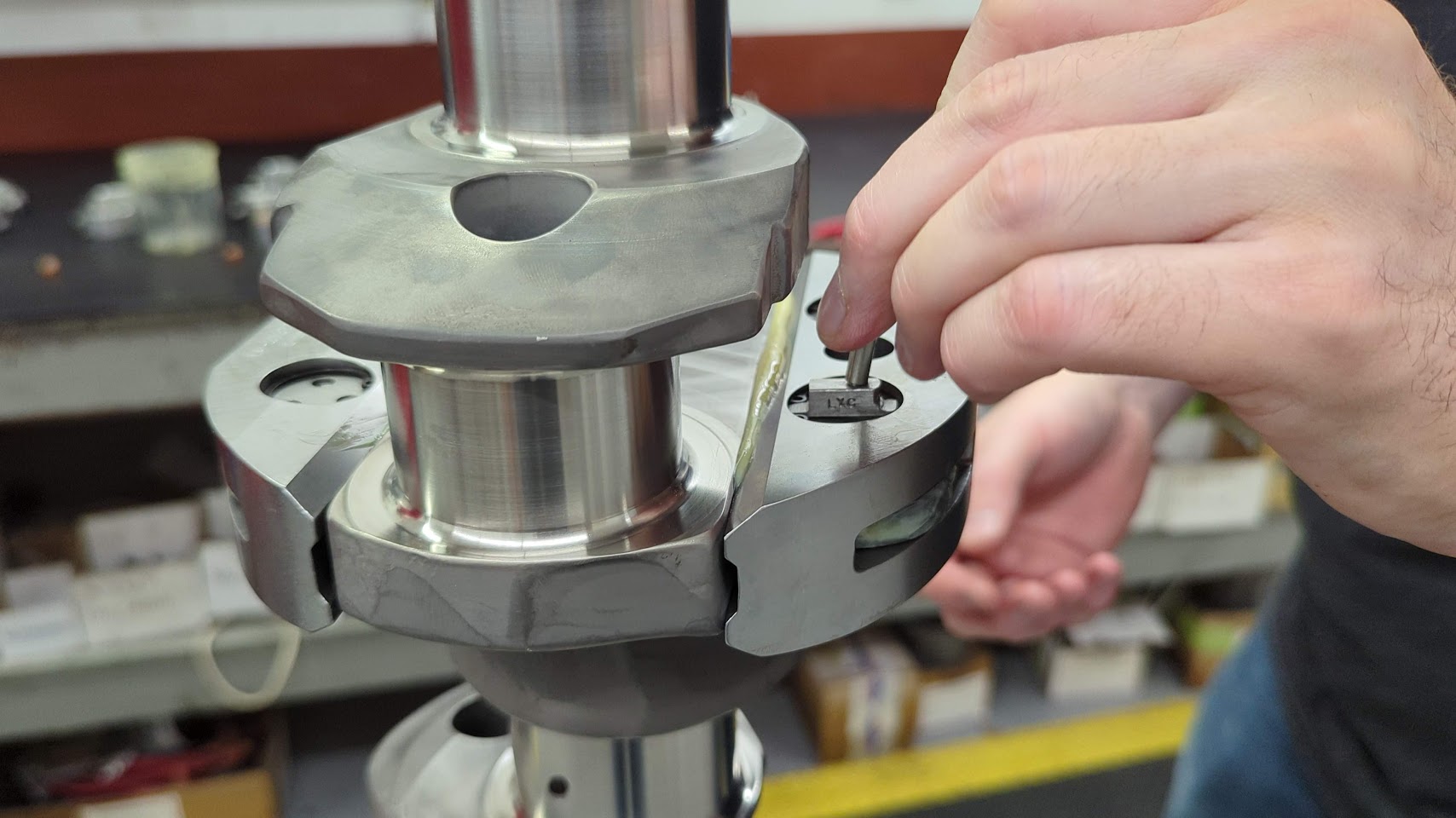
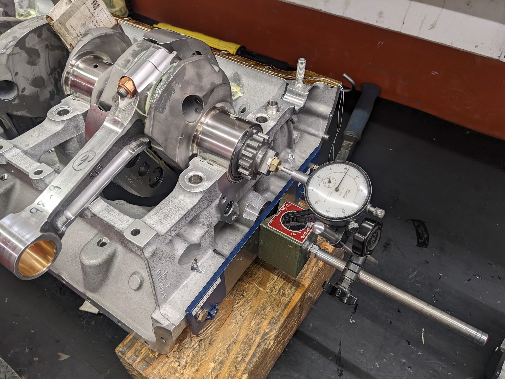
A test gauge is used to ensure that the ring clips are seated correctly.
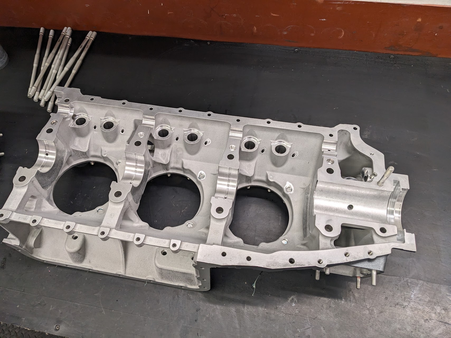
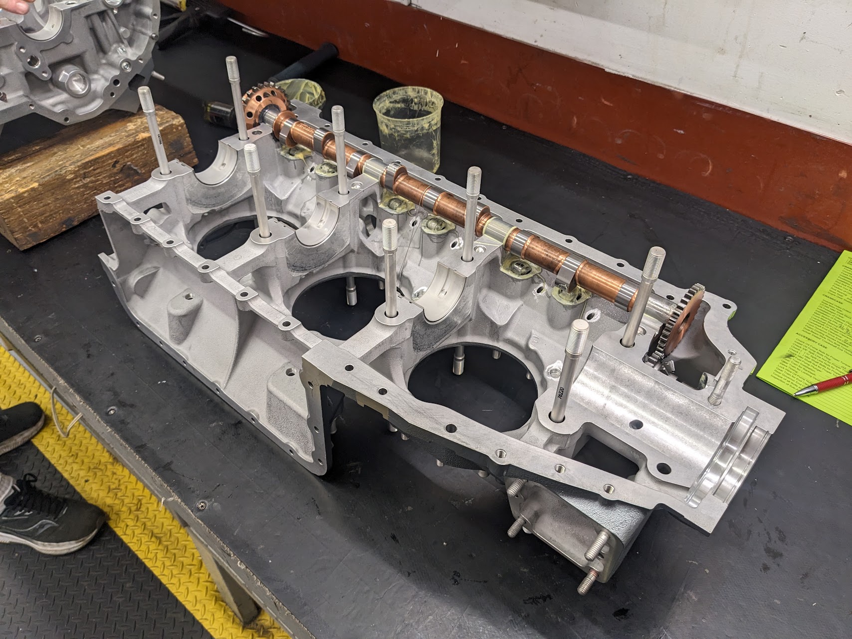
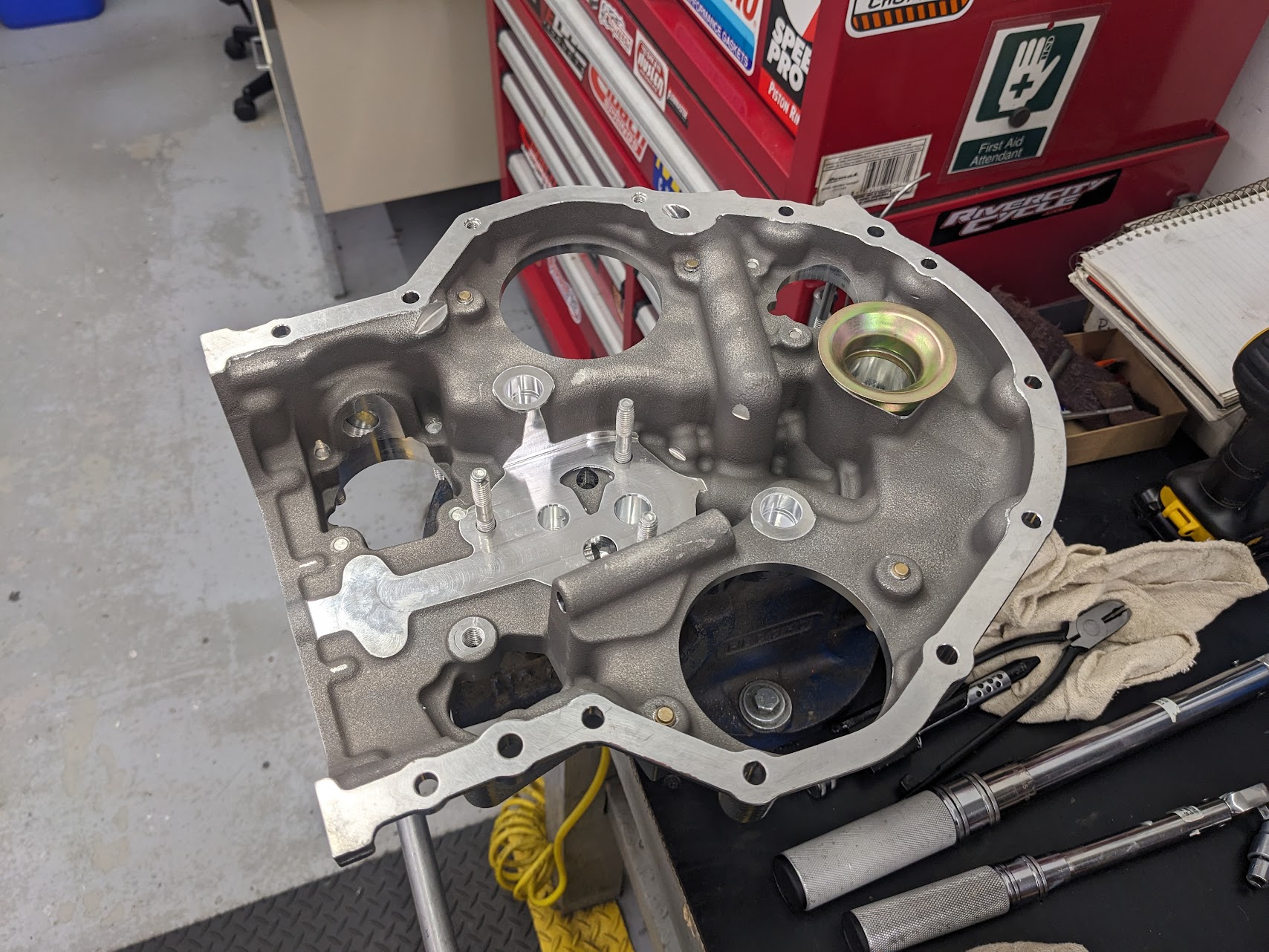
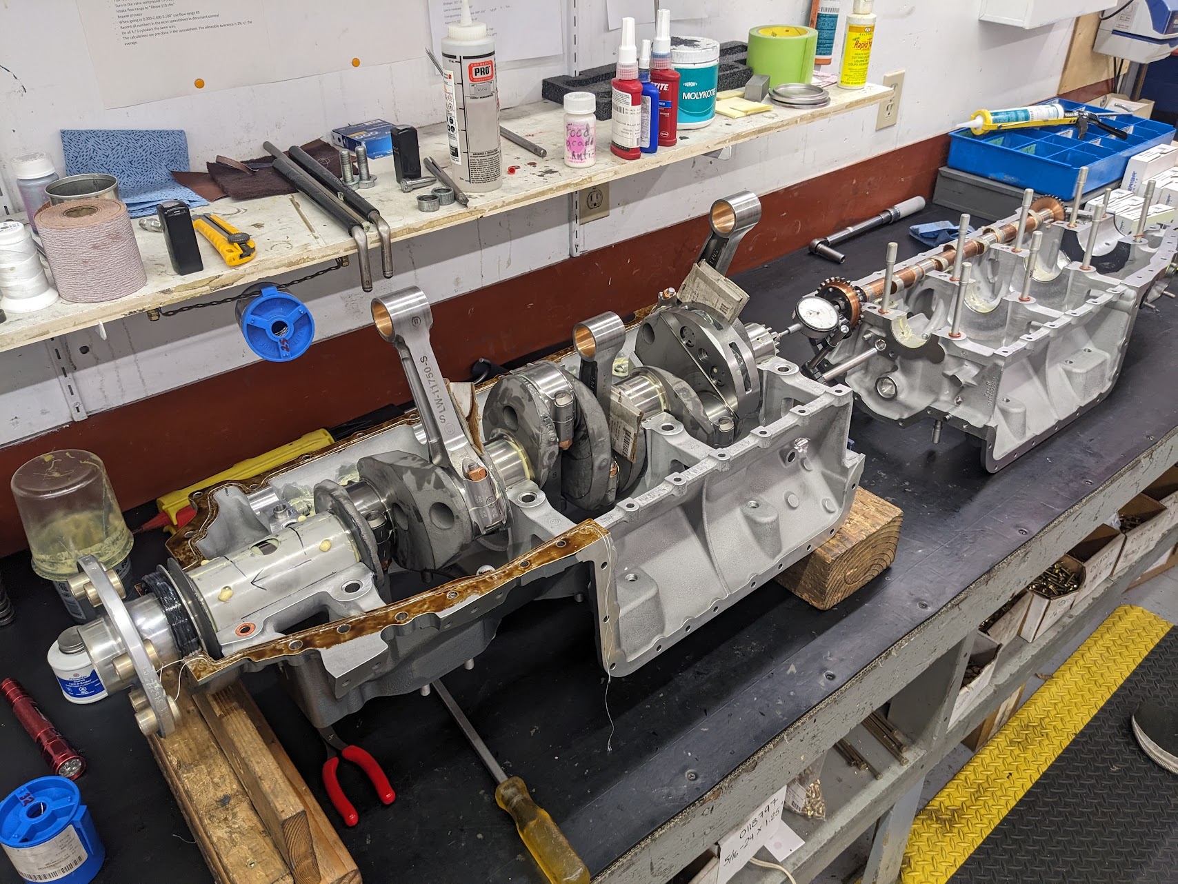
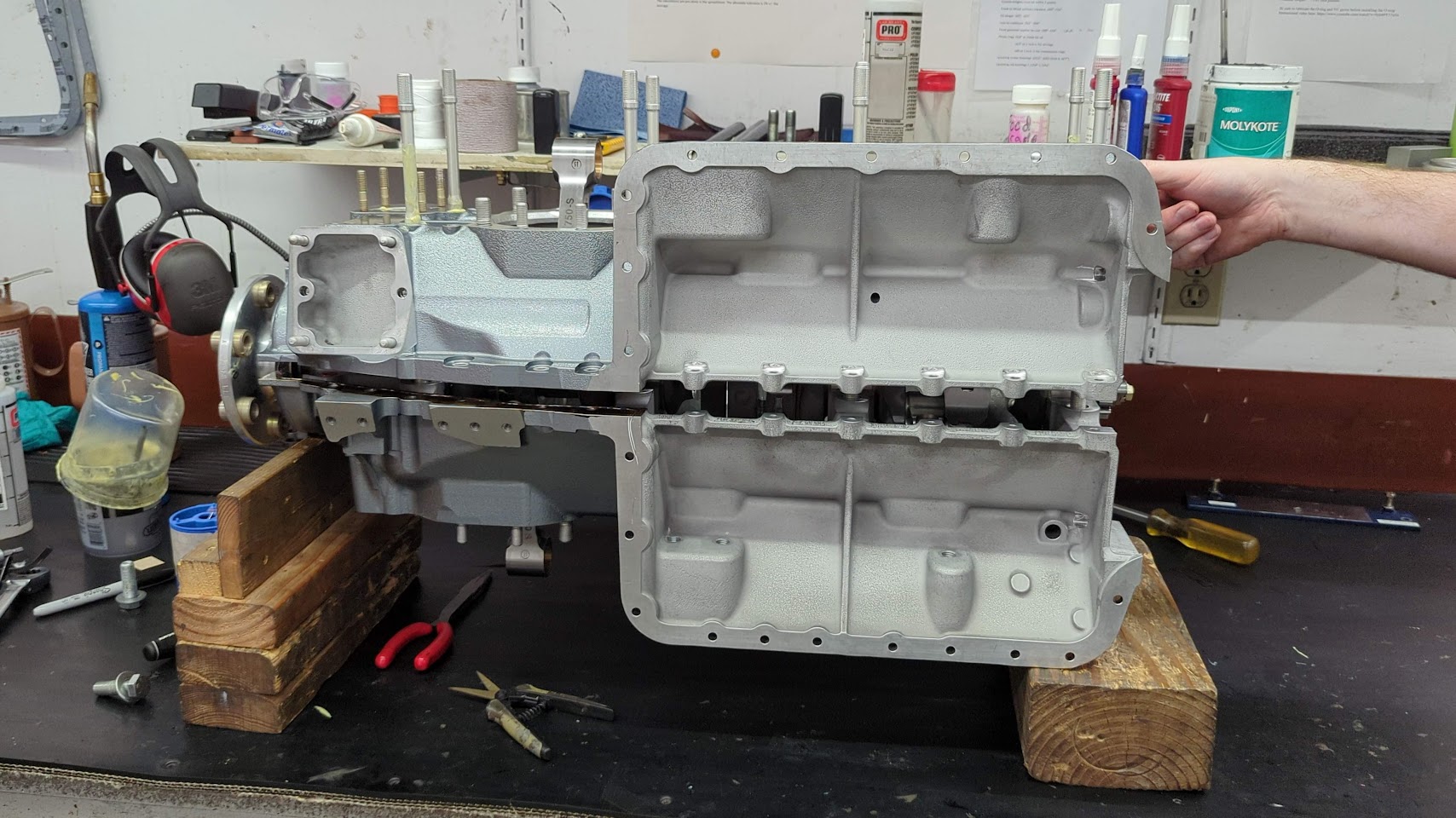
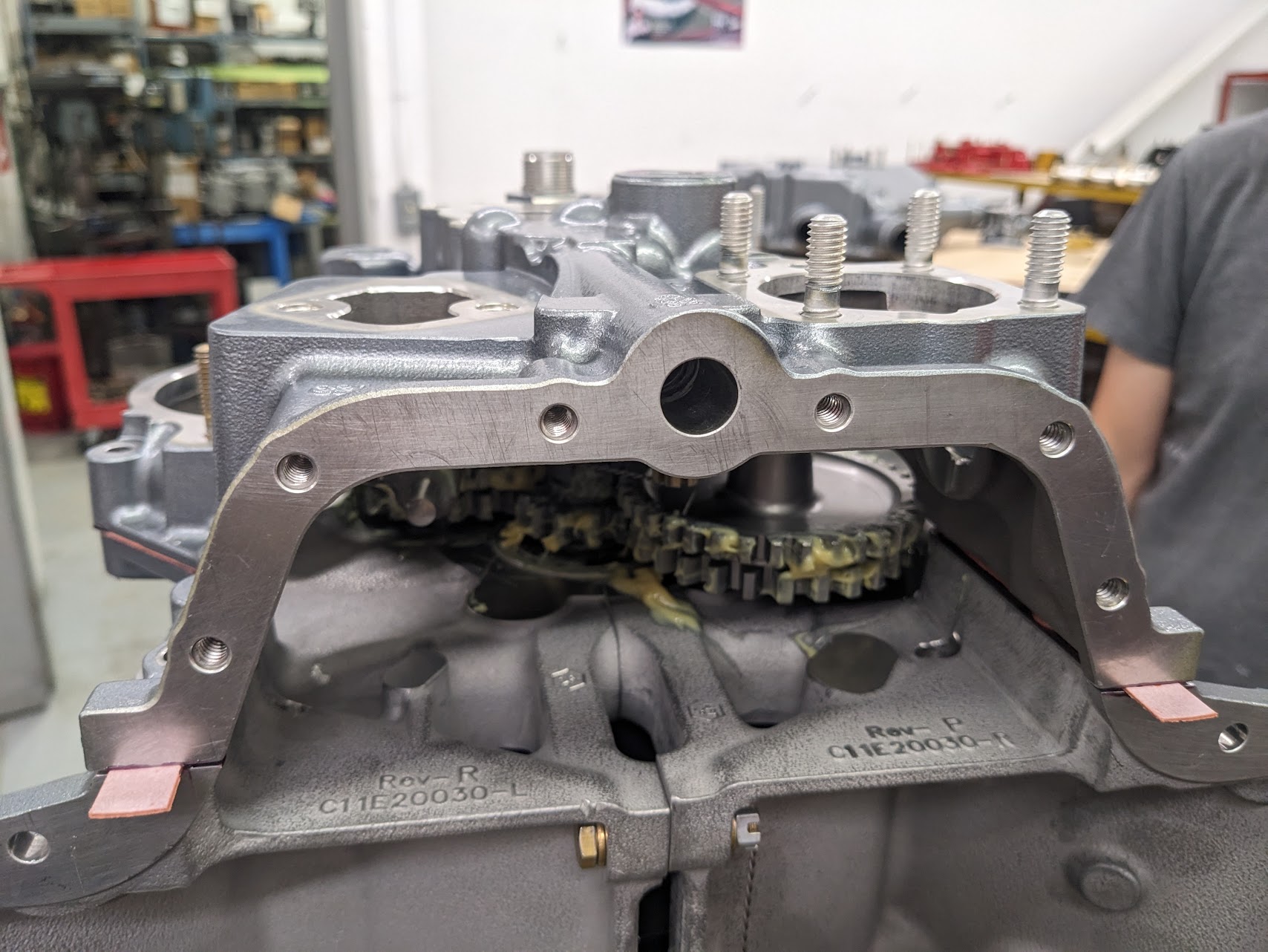
Next up is the crankcase.
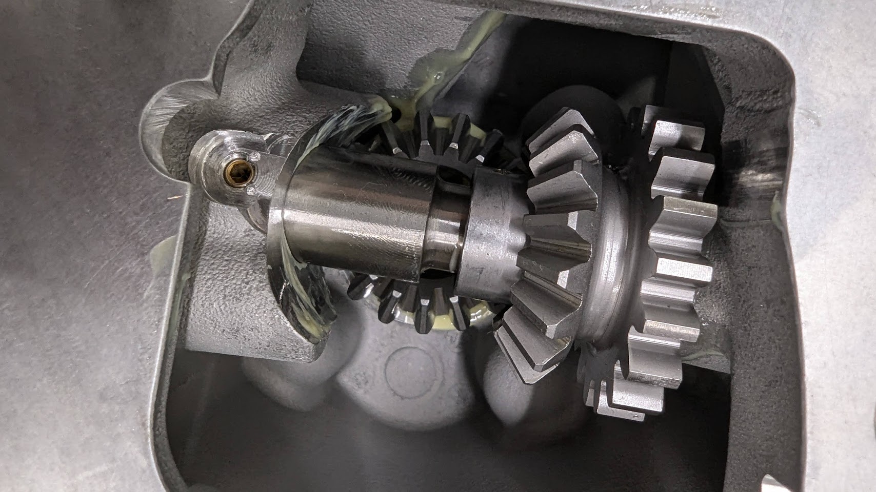
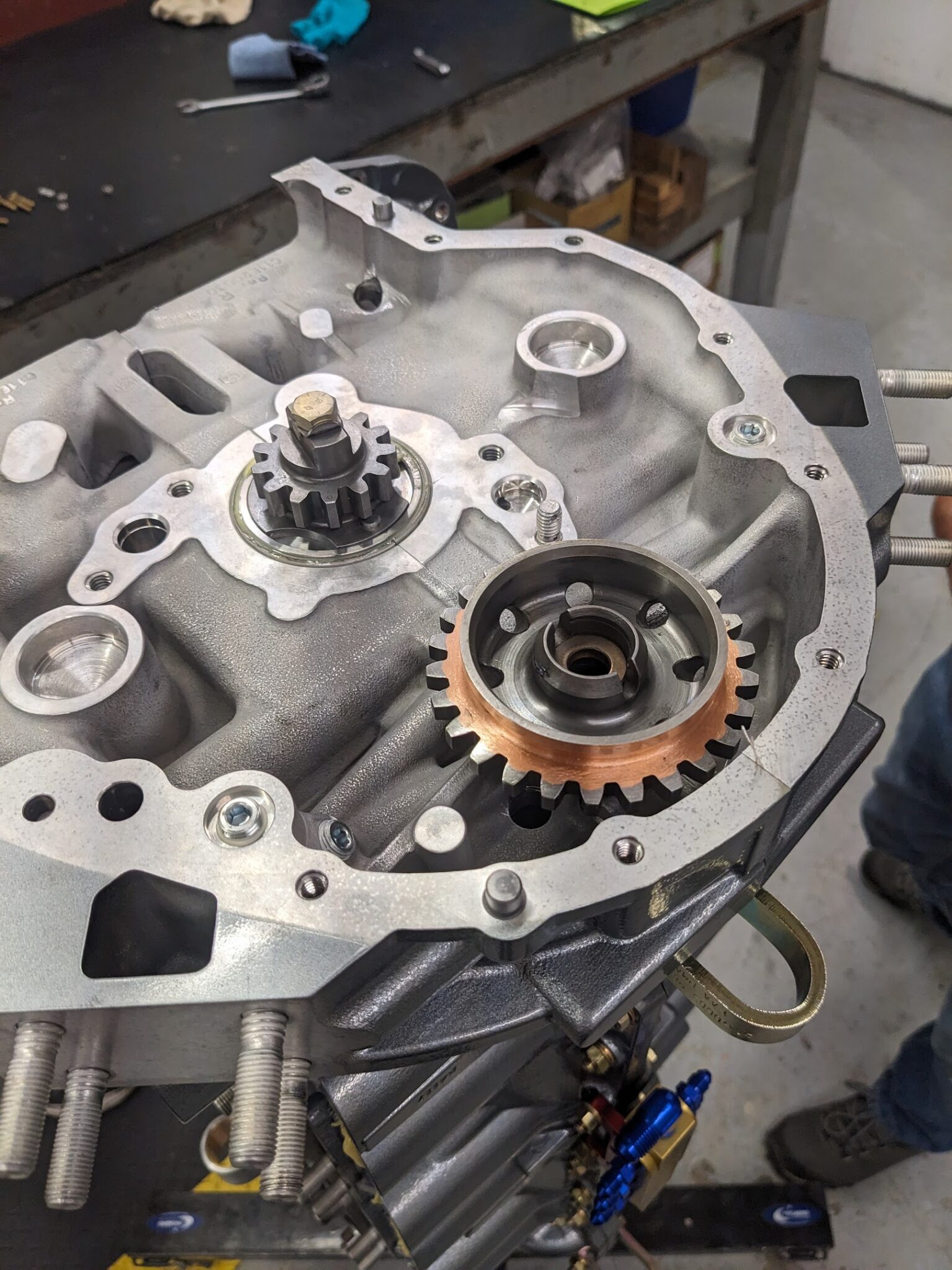
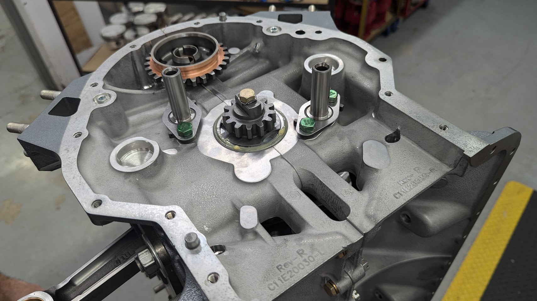
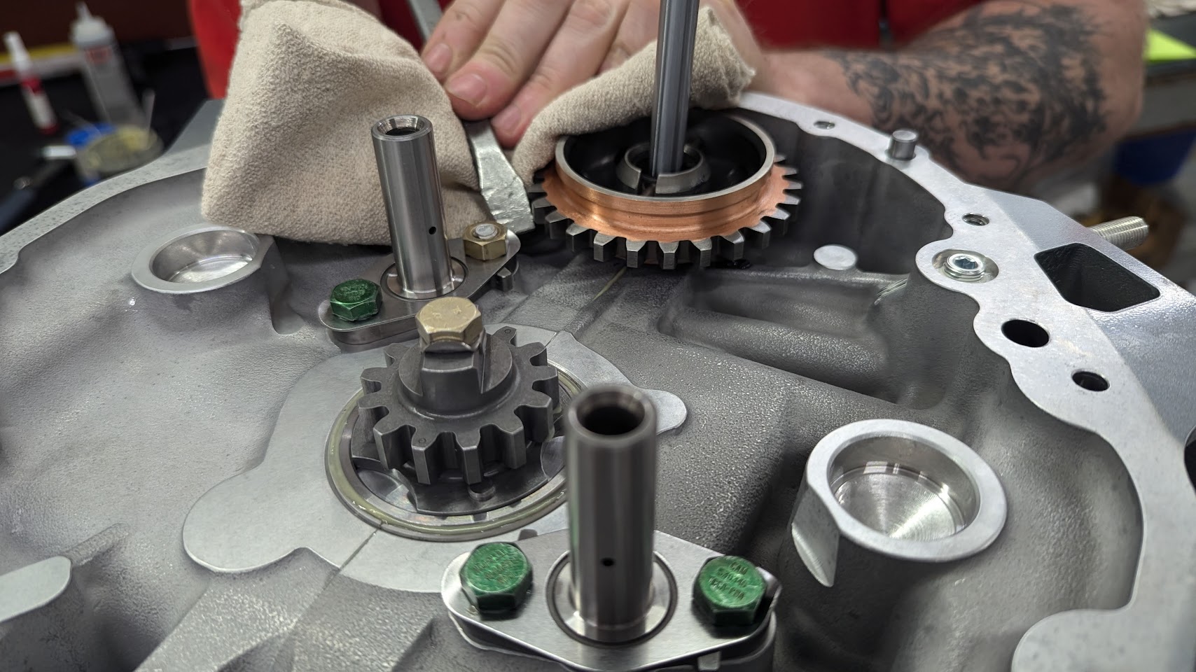
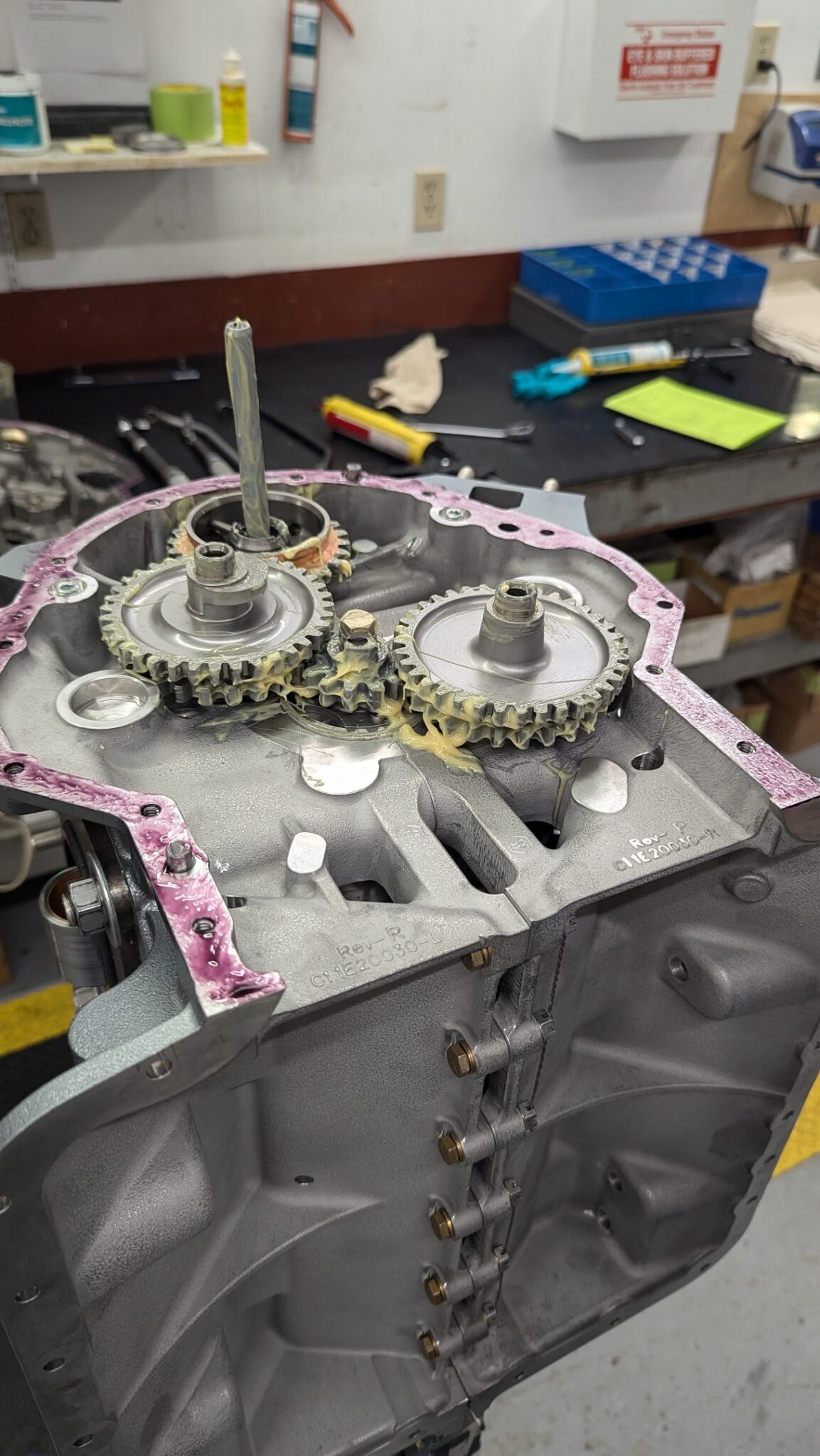
The prop governor drive gears are installed first.
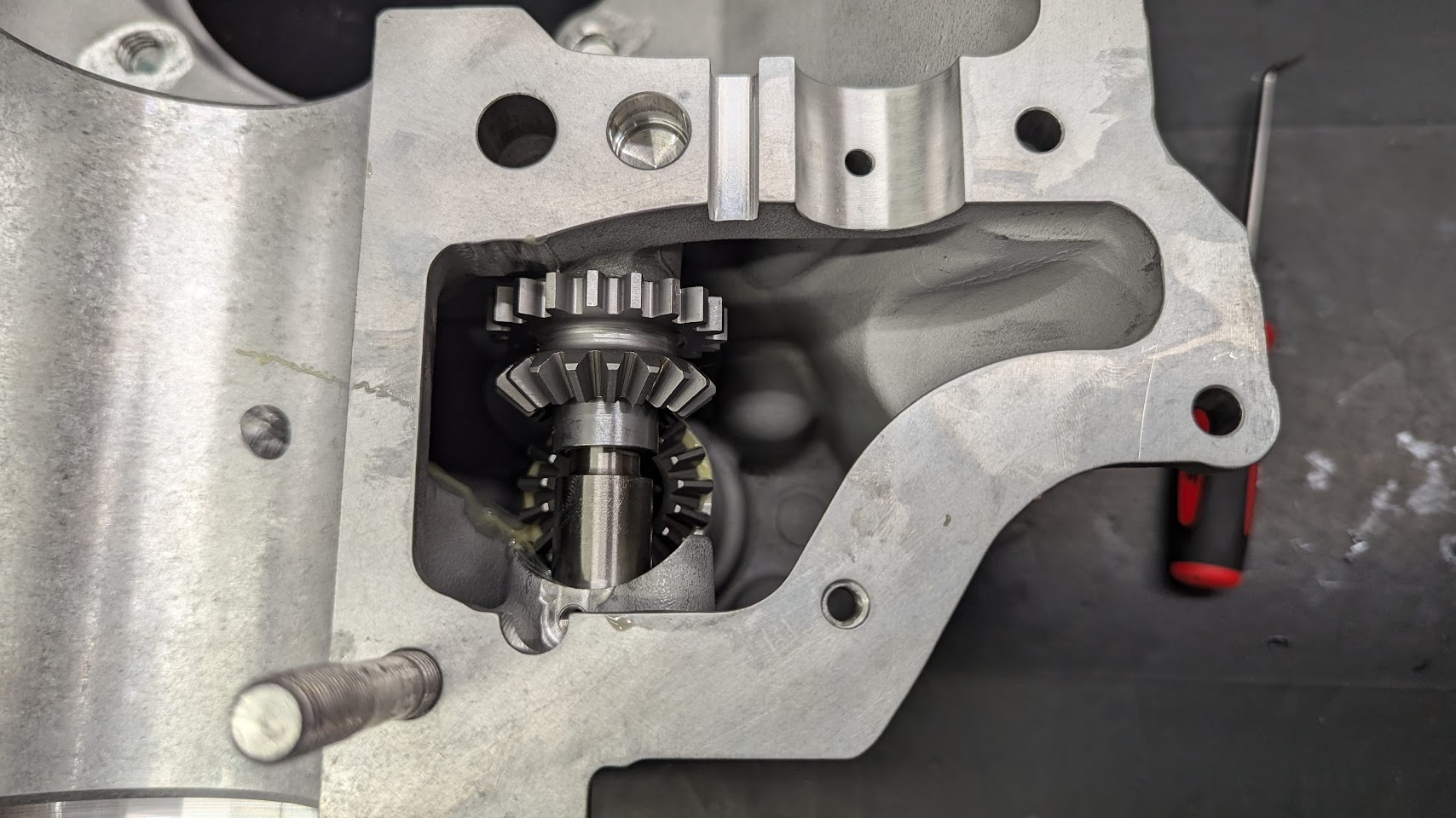

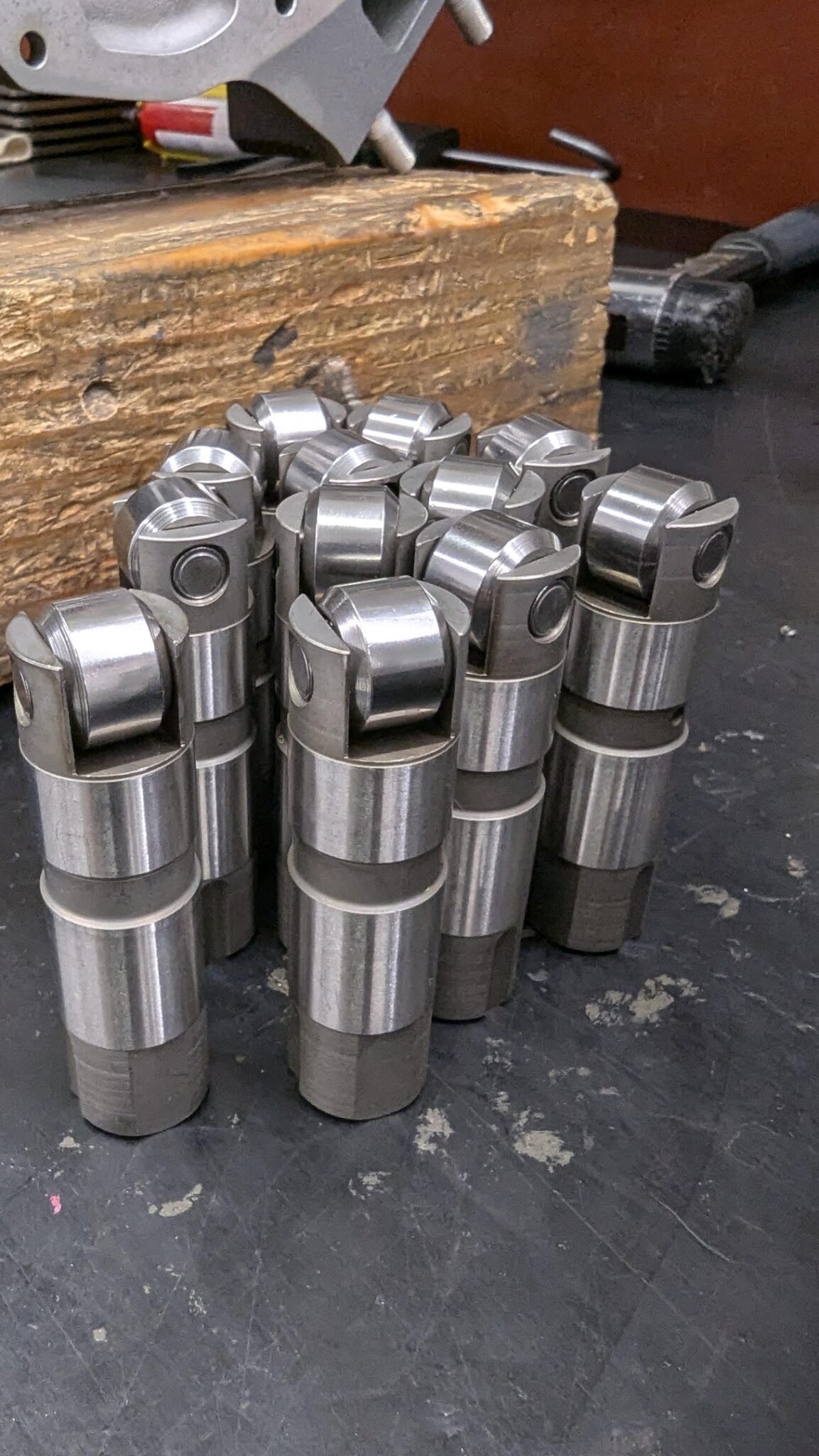
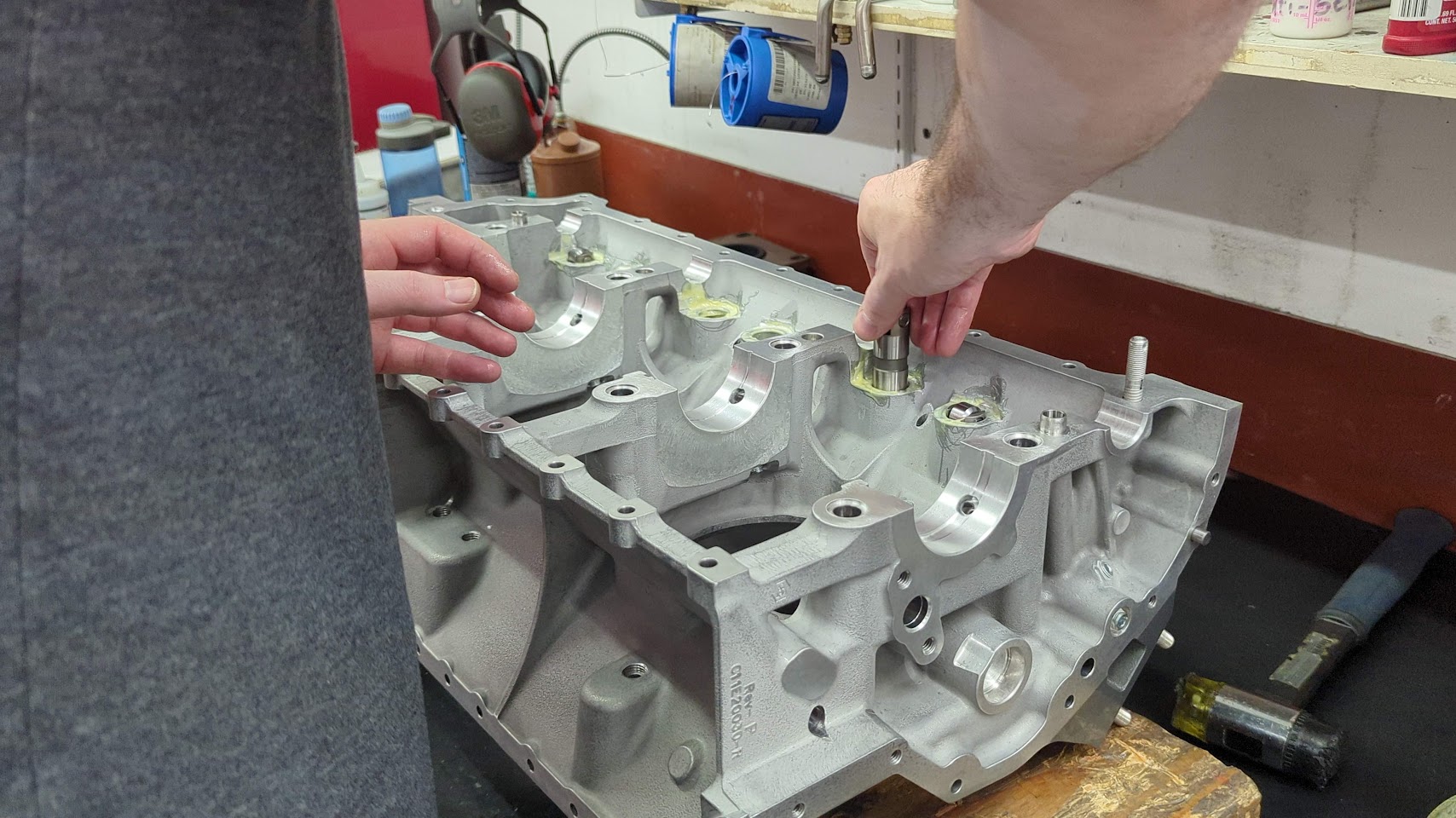
The case through bolts are then set into place and the roller lifters are inserted.
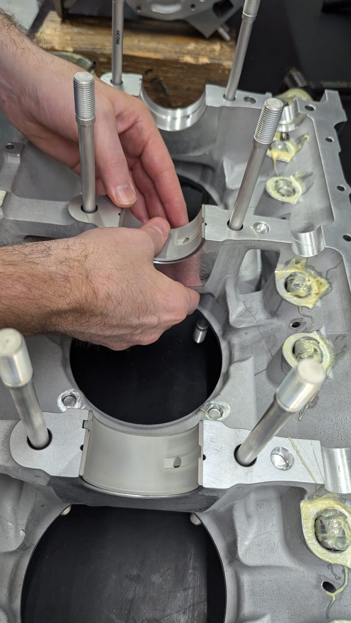
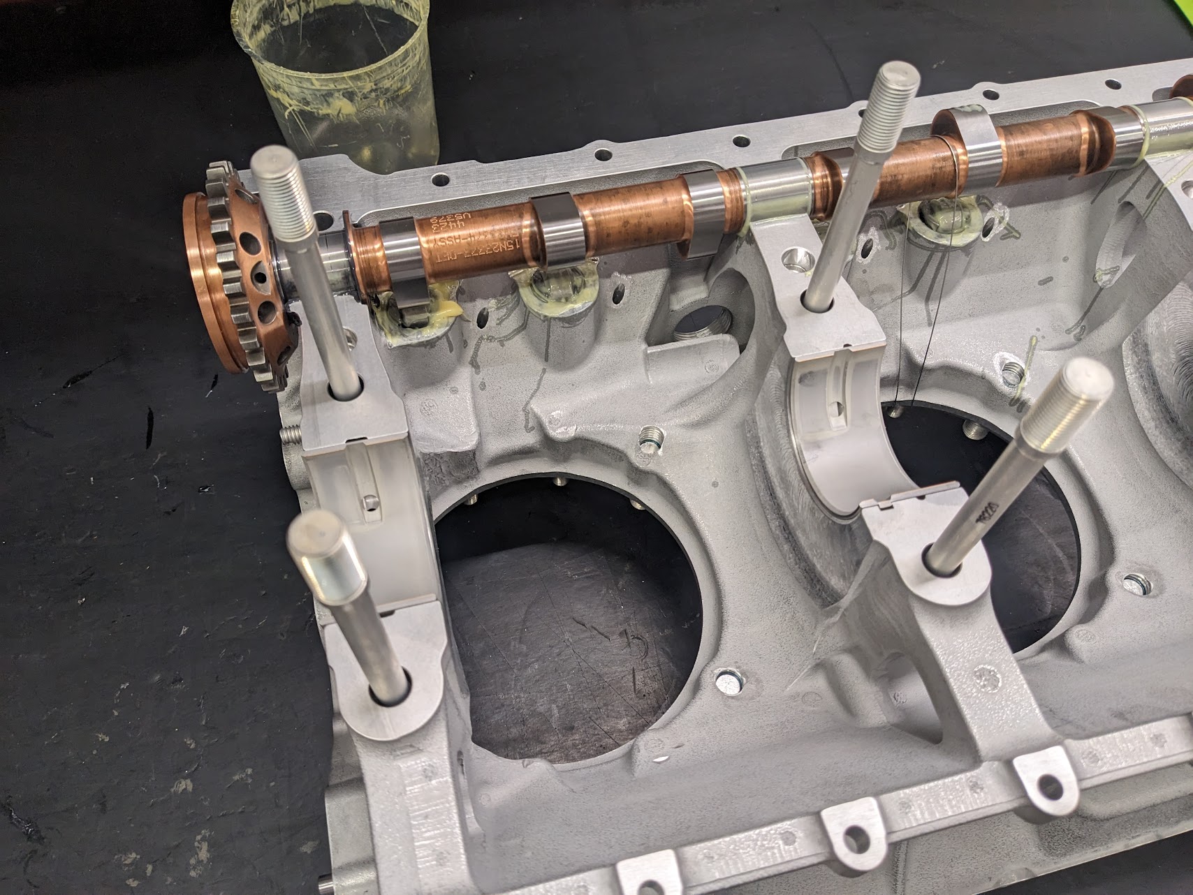
The crankshaft bearings are then inserted into the case.
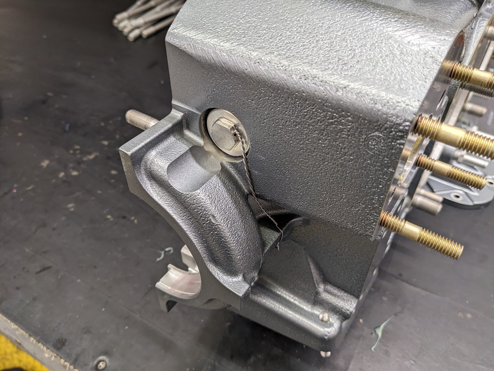
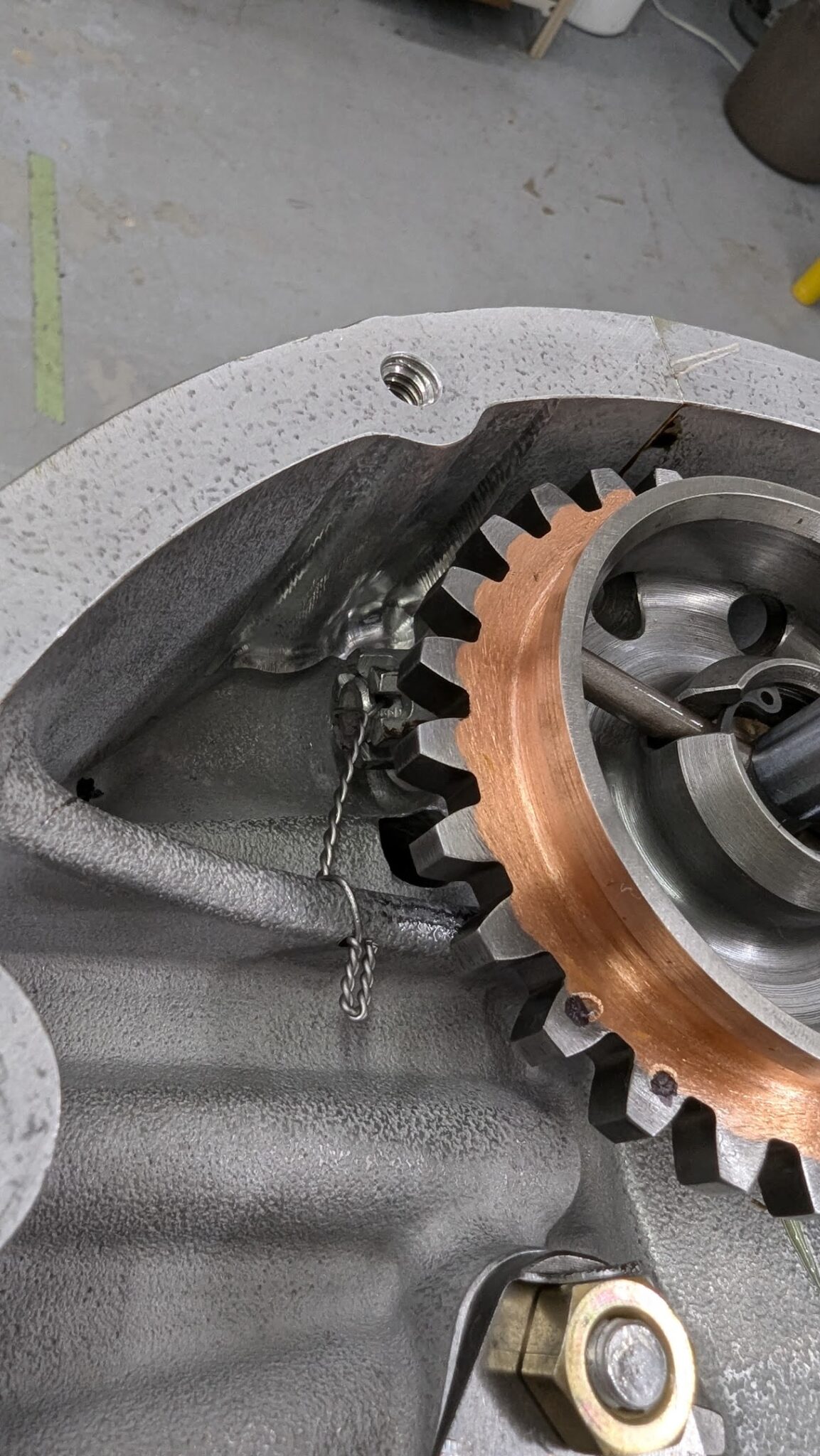
The camshaft is put into place and temporarily secured with a loop of safety wire to hold it in place when the case half is flipped over to join the halves.

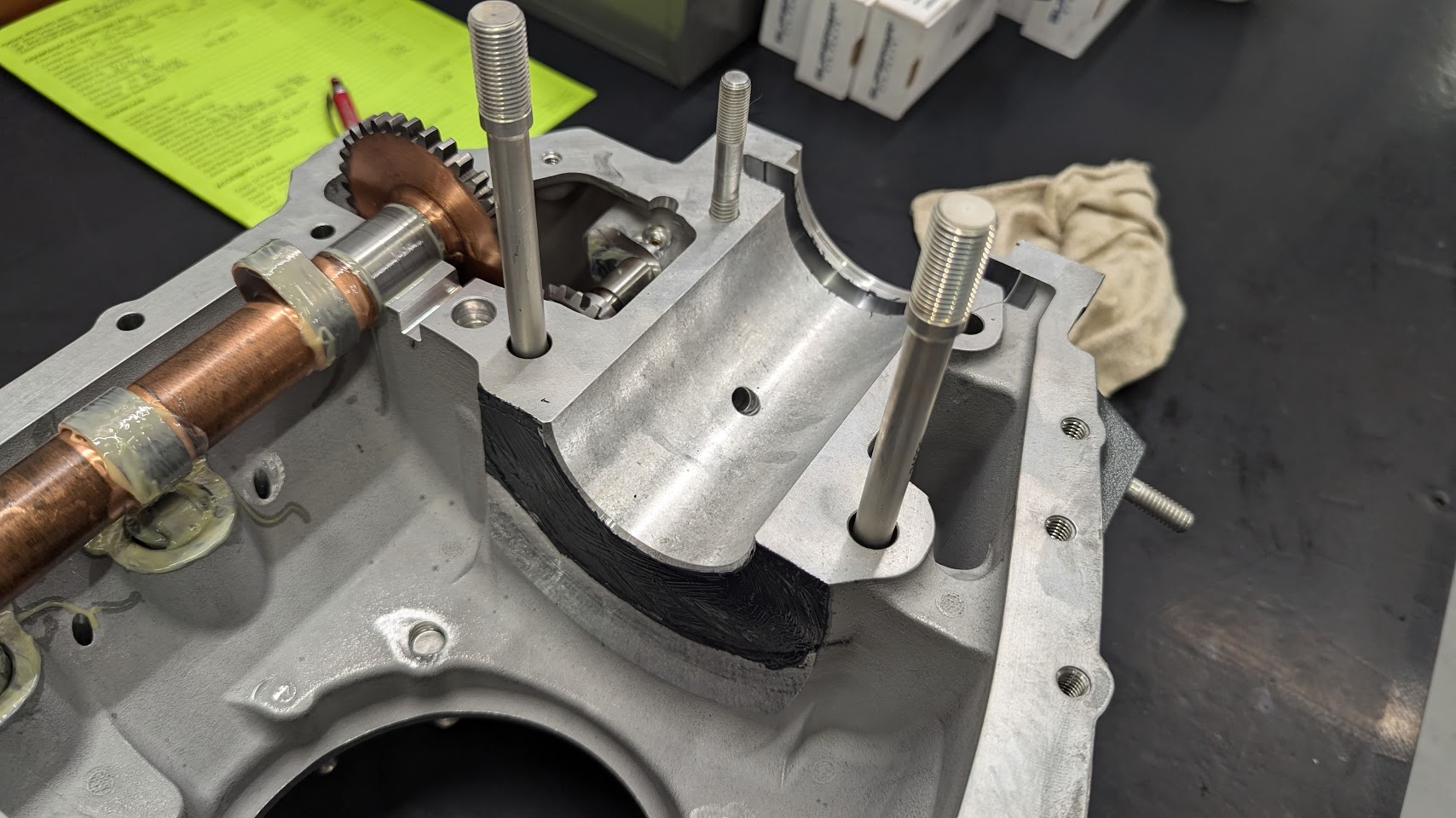
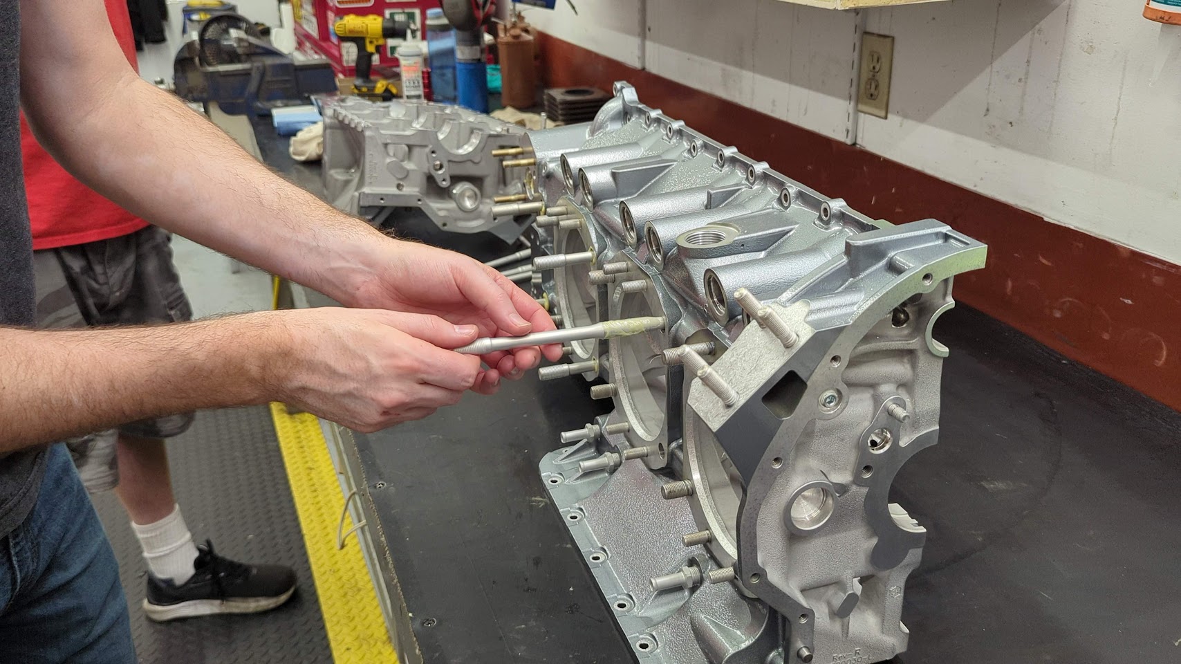
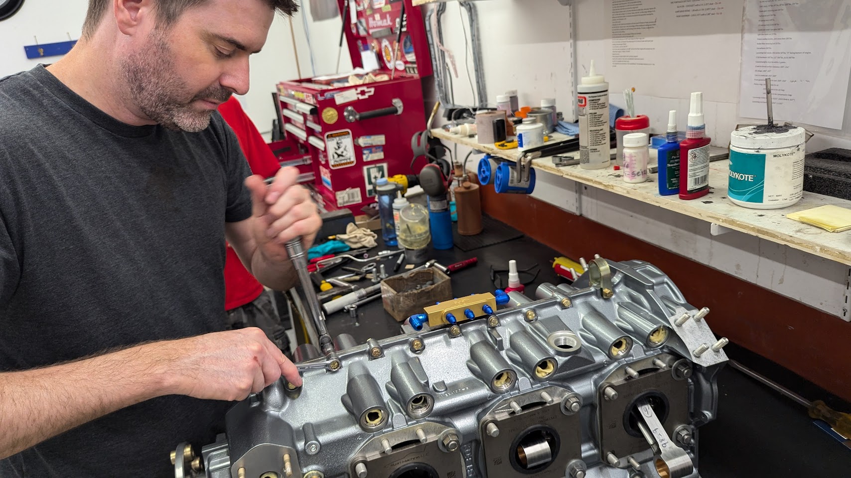
O-rings are used around each bolt. Aero Sport machines the slots for these in the case (Lycoming does not do this work on the case for some reason and this is left to the assembler).
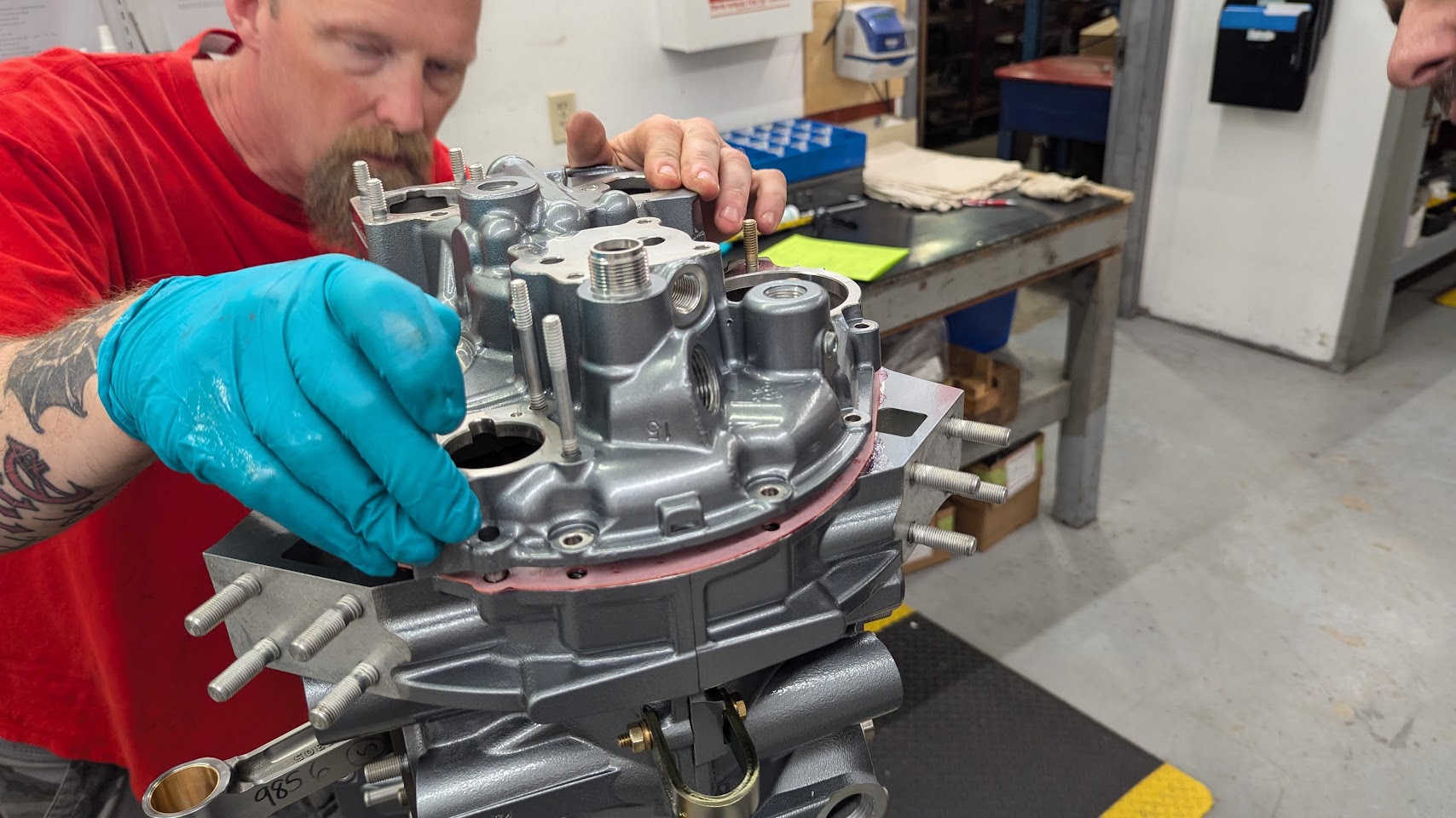
Next up is the accessory housing.
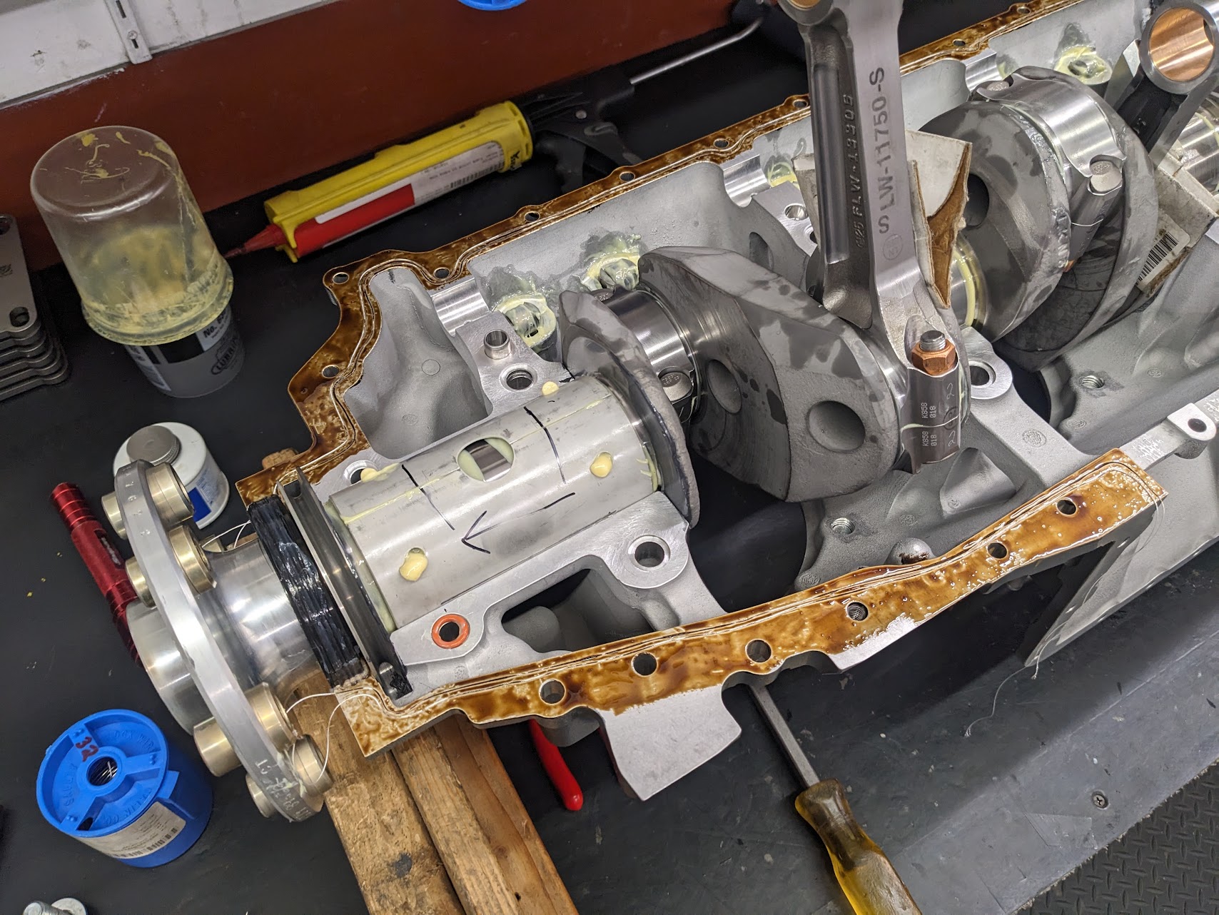
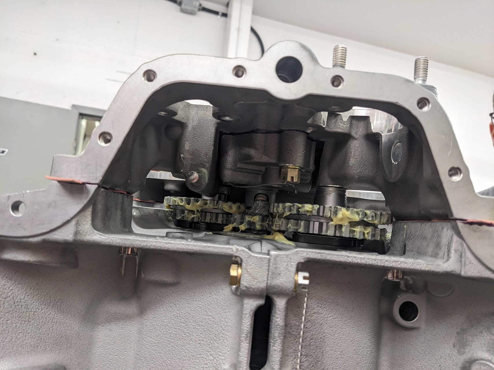
The mechanical oil pump is installed first.
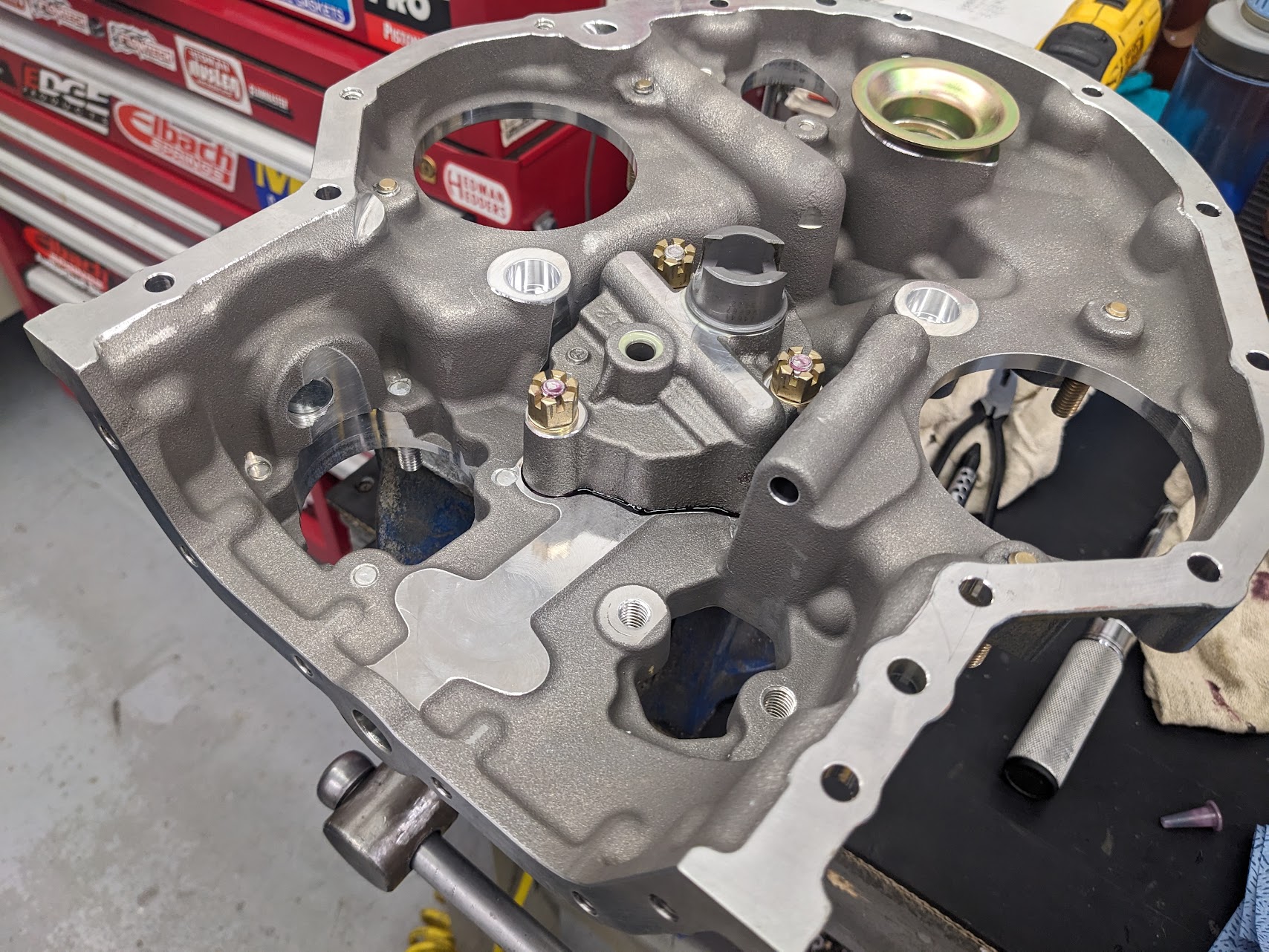
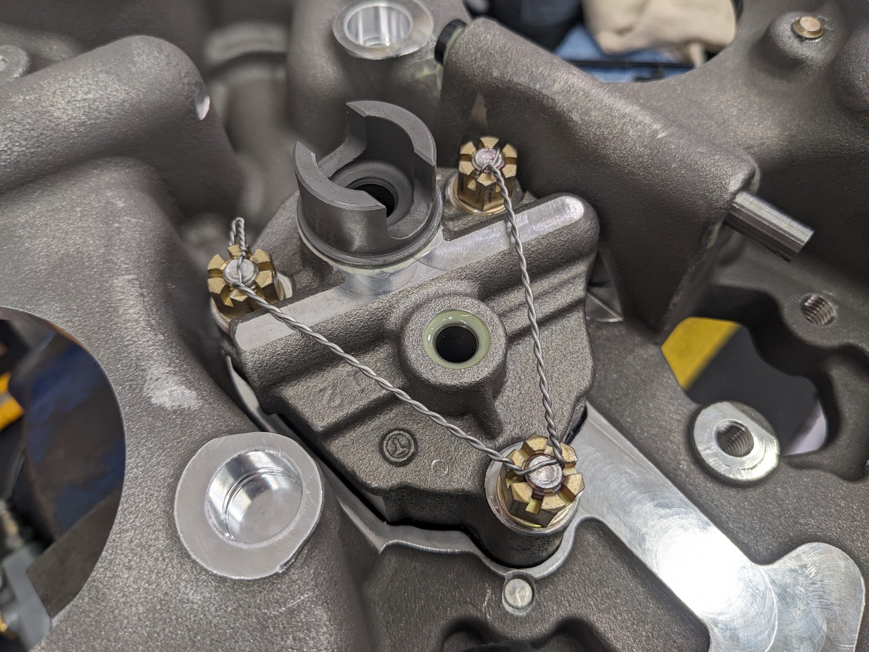
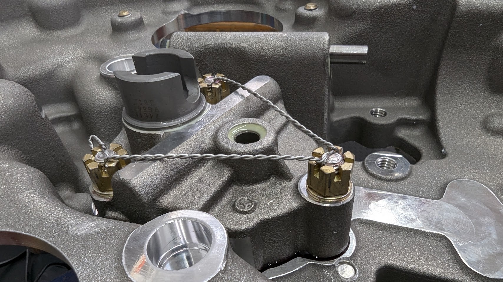
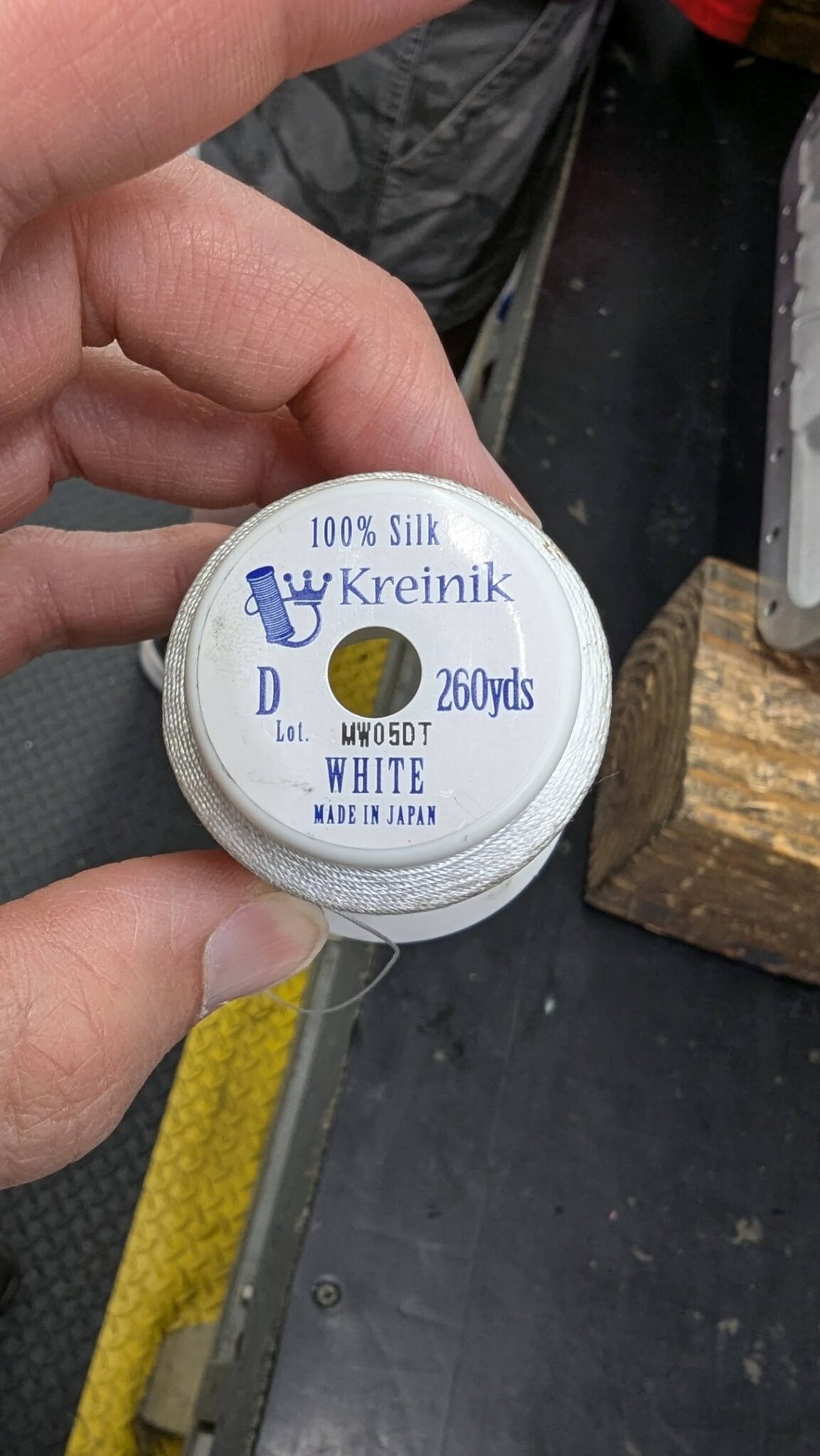
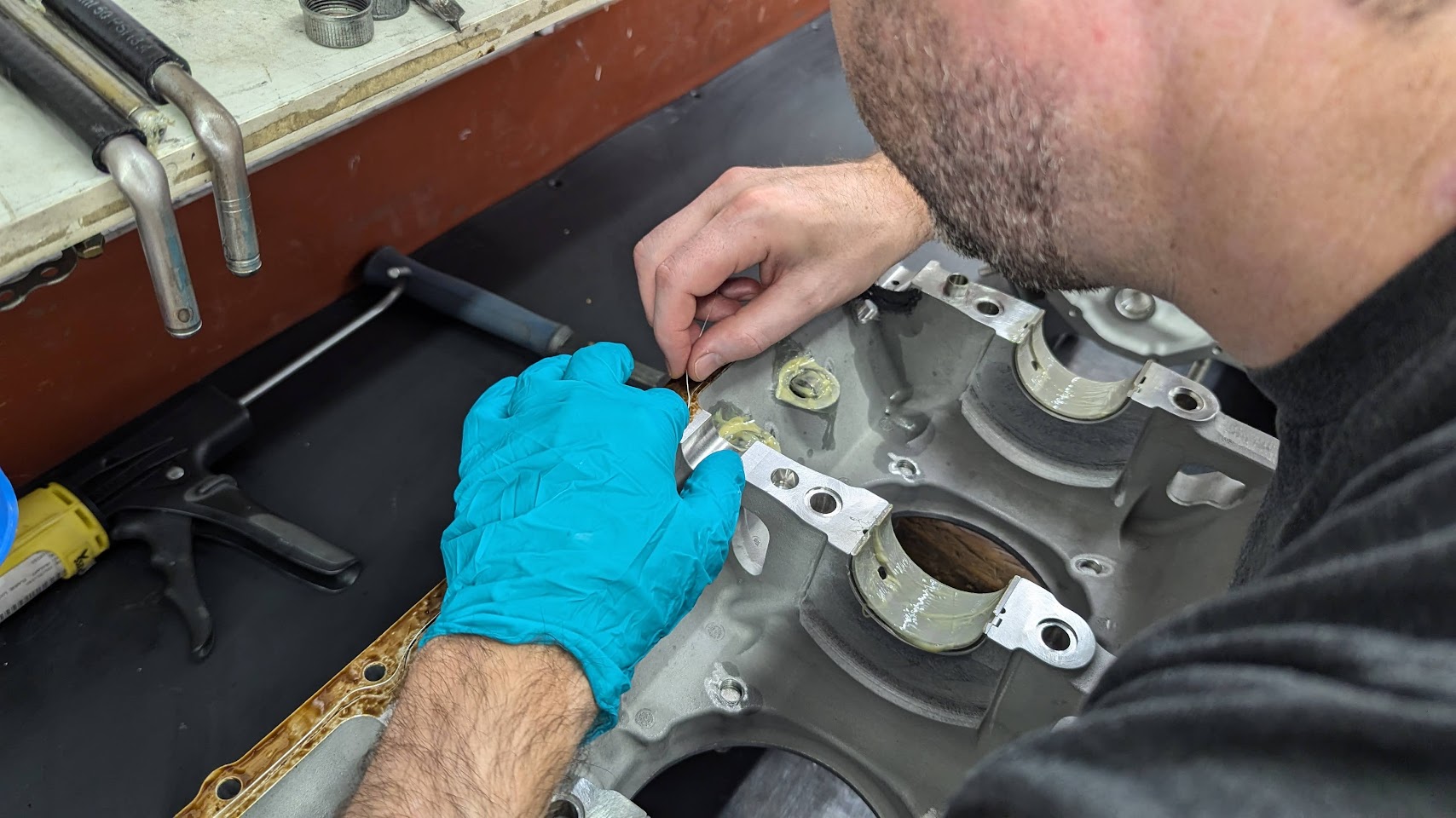
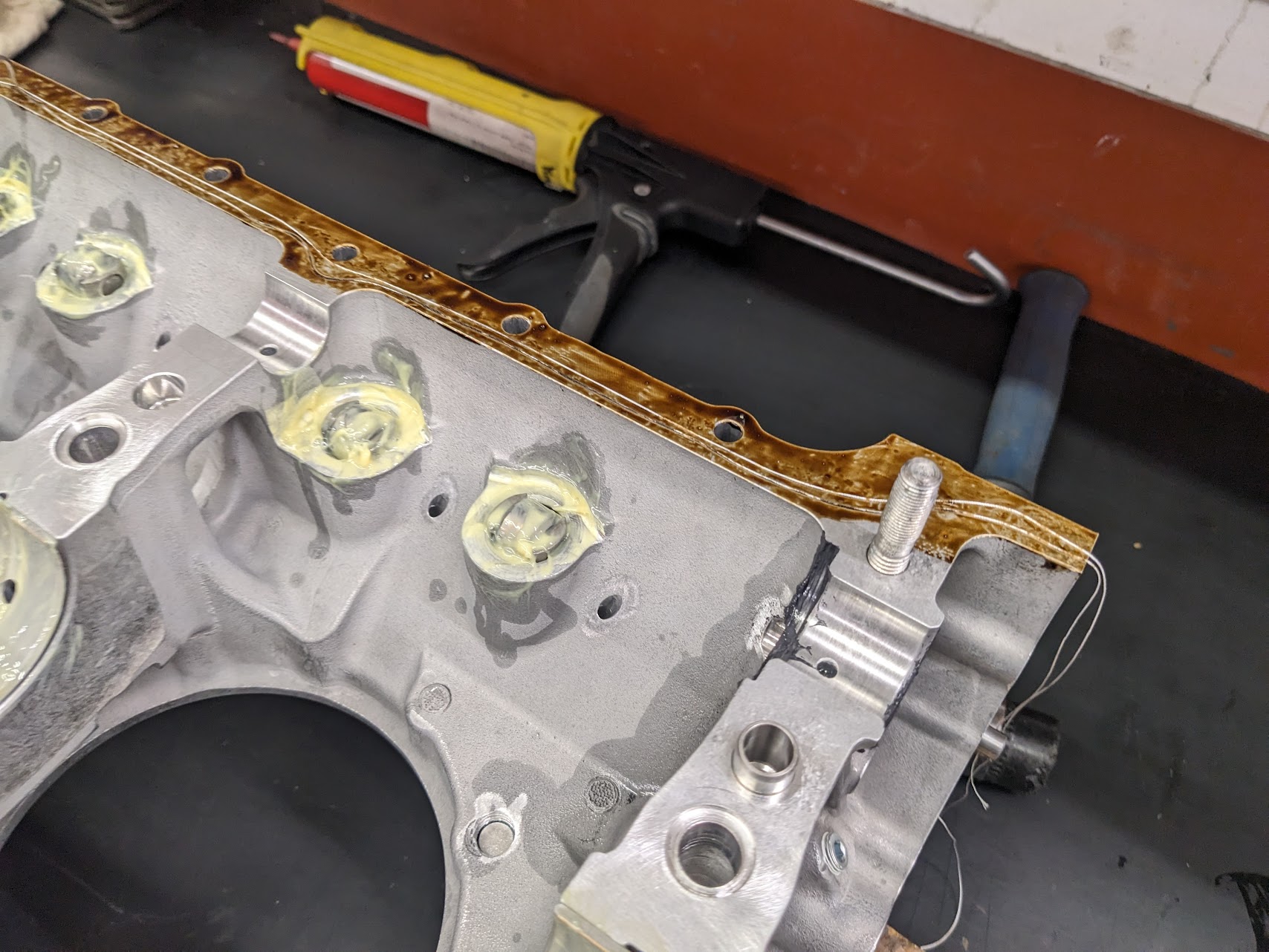
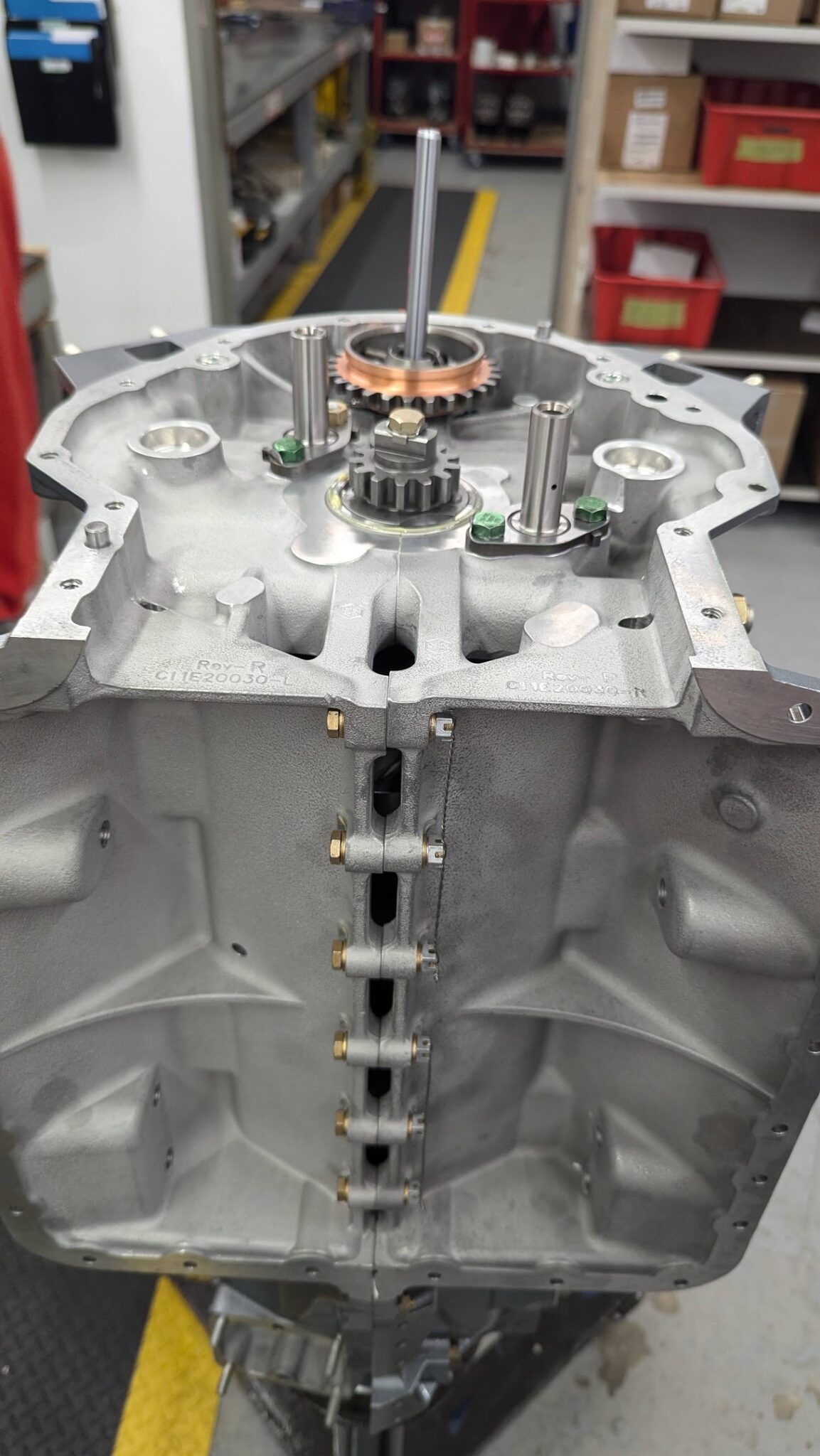
Next up is adding the silk thread that seals the case. A layer of flange sealant is added first, then two silk threads are added, about 1/8″ apart.
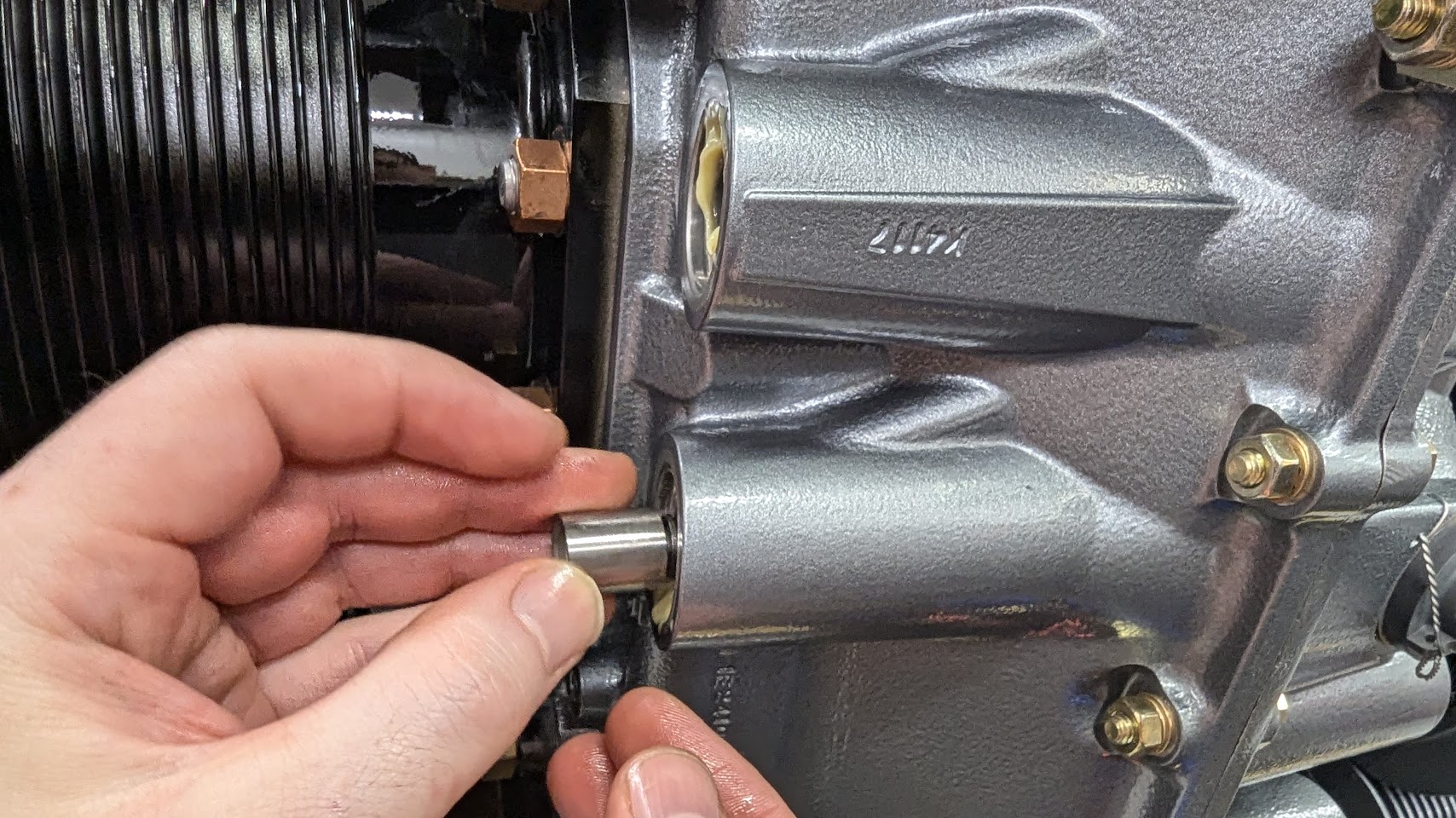
Molykote is brushed on in several areas for the first start. The prop nose seal is installed.
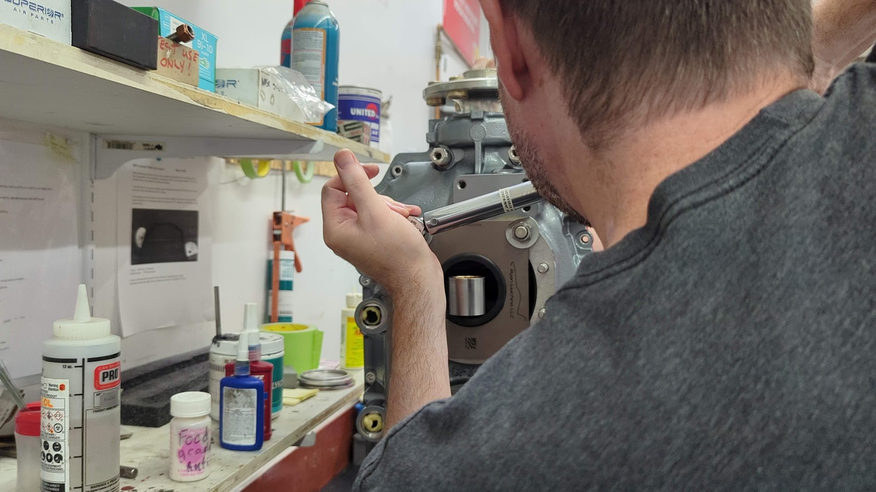
The crankshaft is then installed and the forward/aft end play is checked for spec (.012″).
A secondary inspection is performed at all critical stages with sign-off before proceeding. All torque values are triple-checked.
The case halves are then joined.
Plates are used at this stage to pull the halves together. These are removed later when the cylinders are installed.
Bolts are installed around the case flanges.
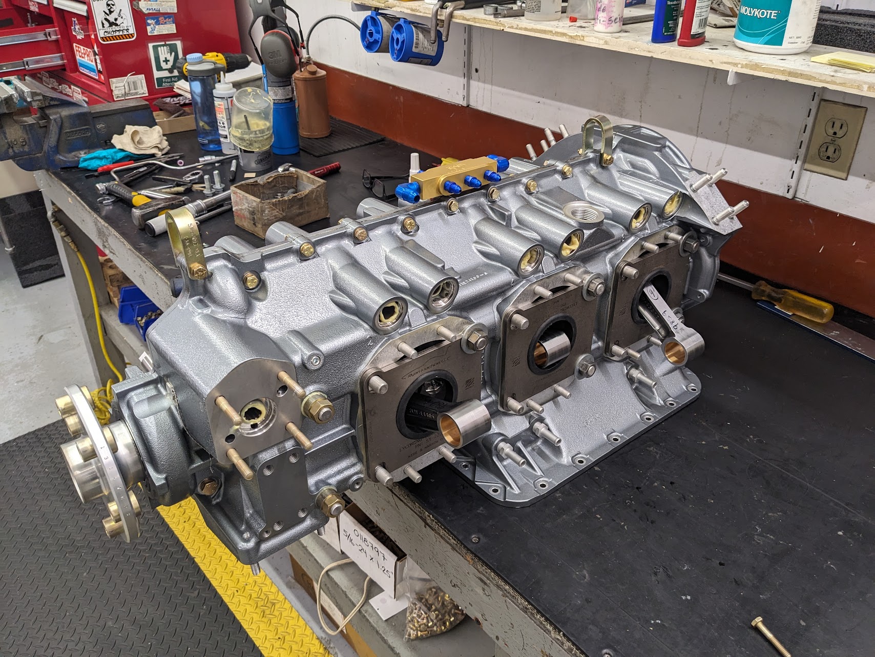
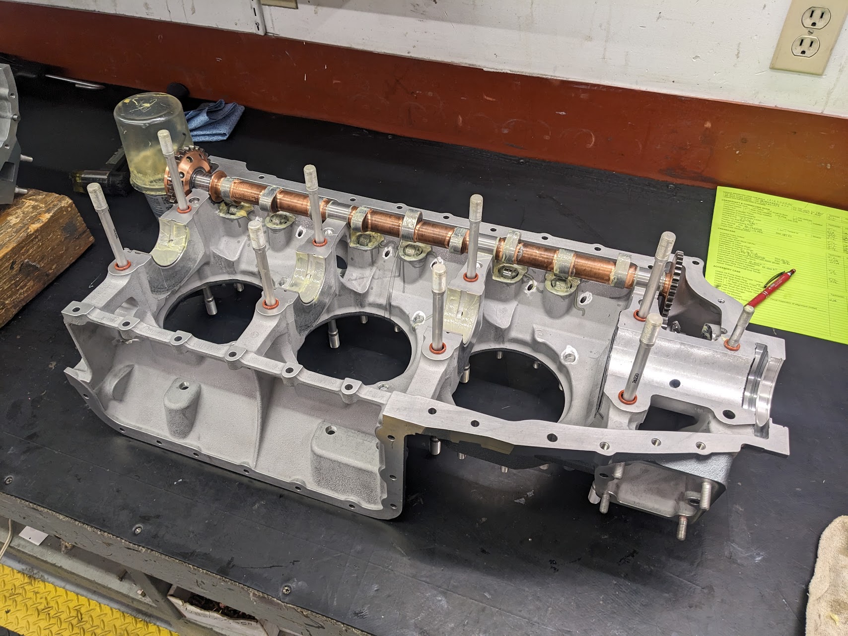
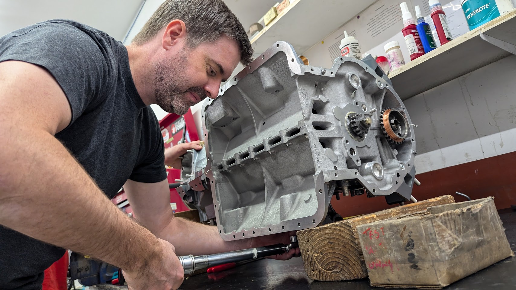
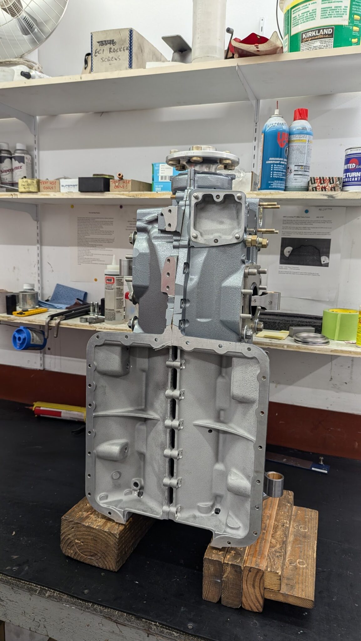
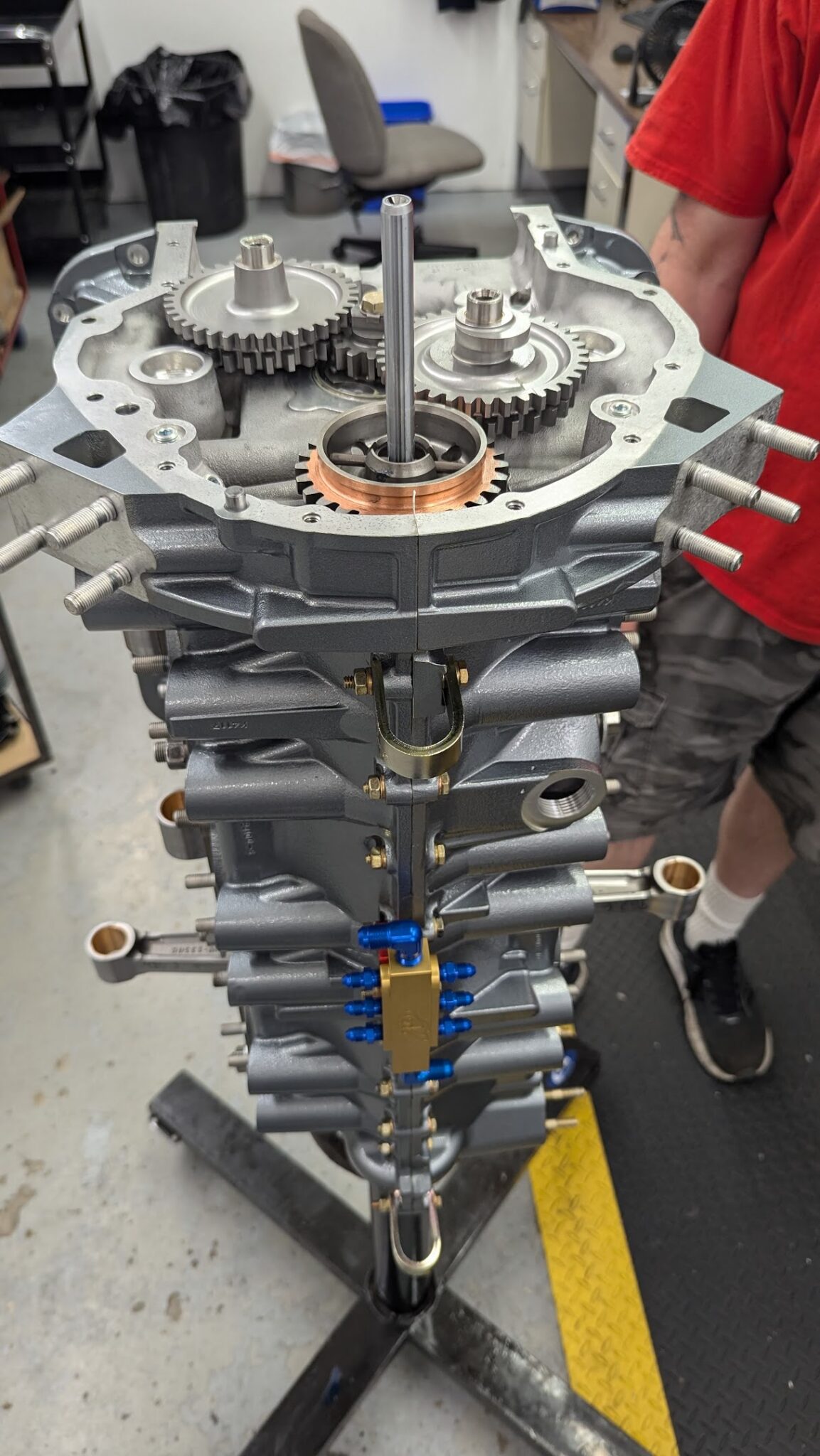
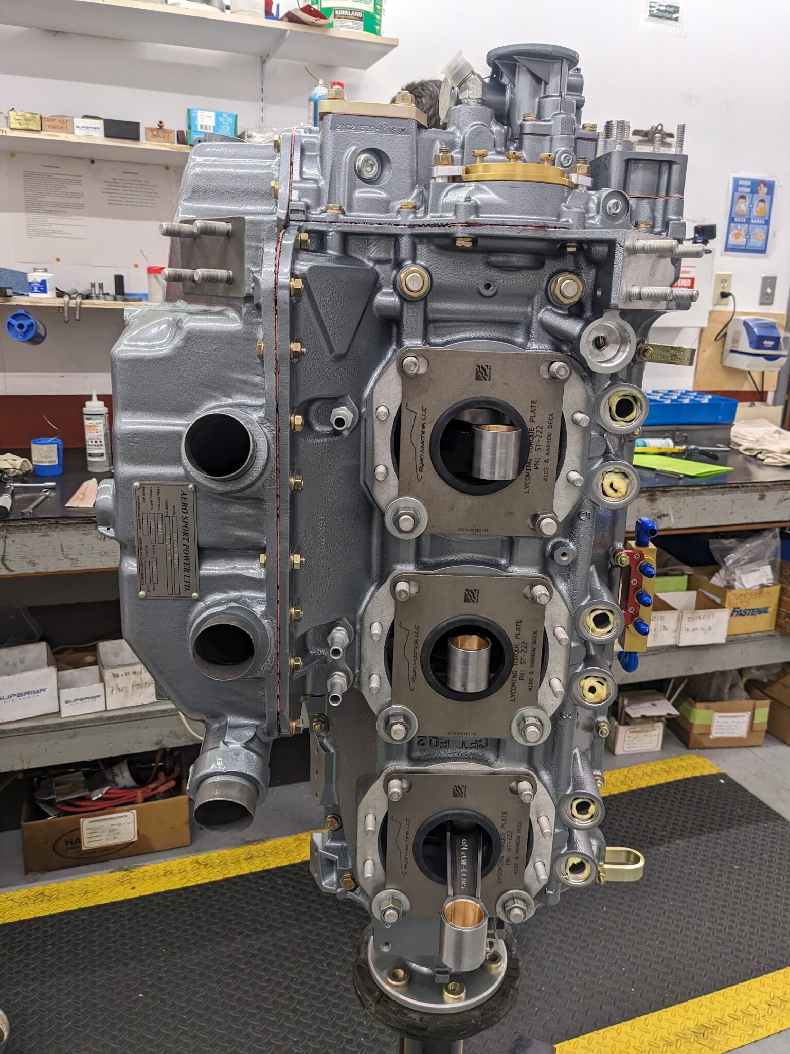
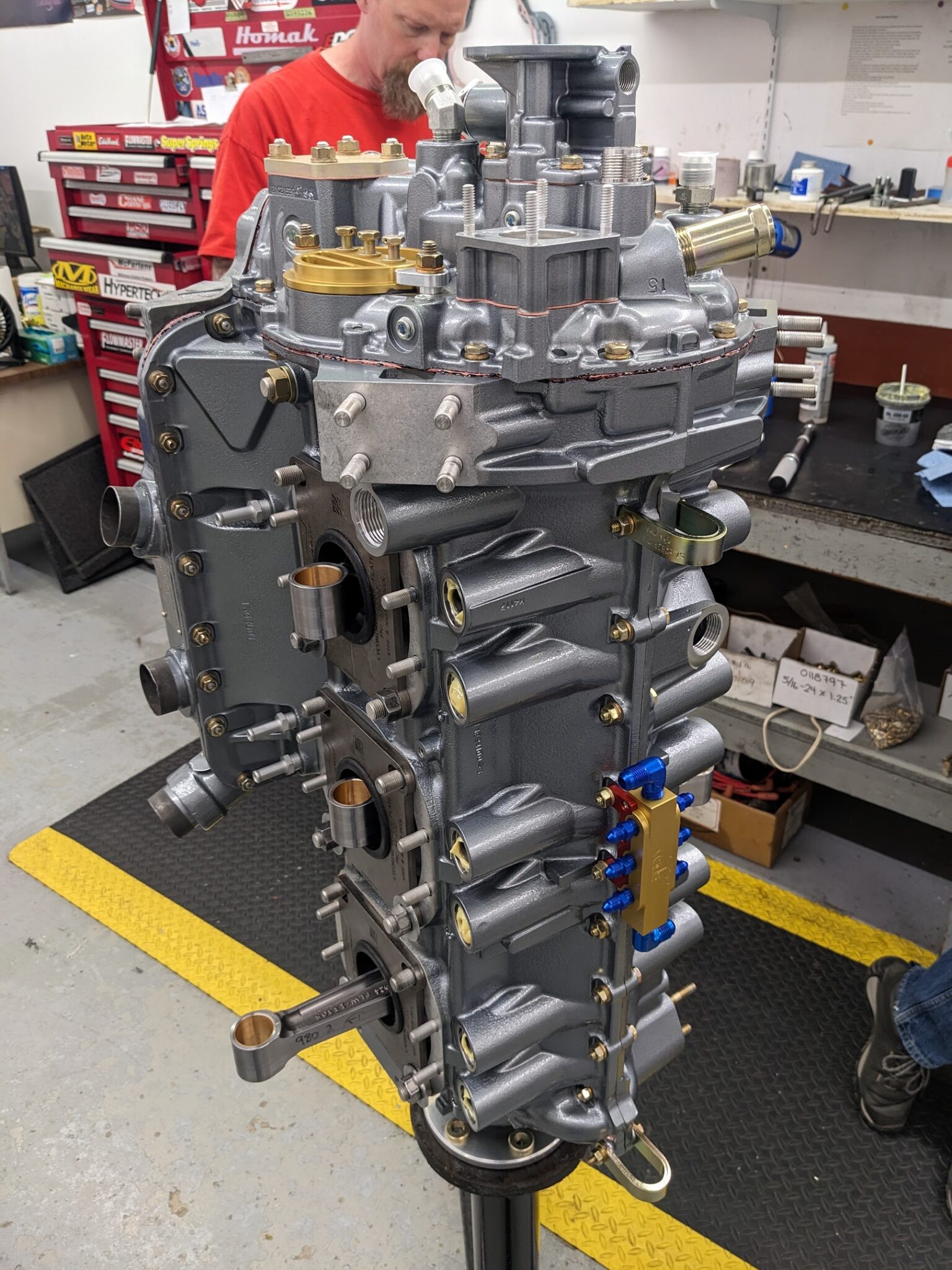
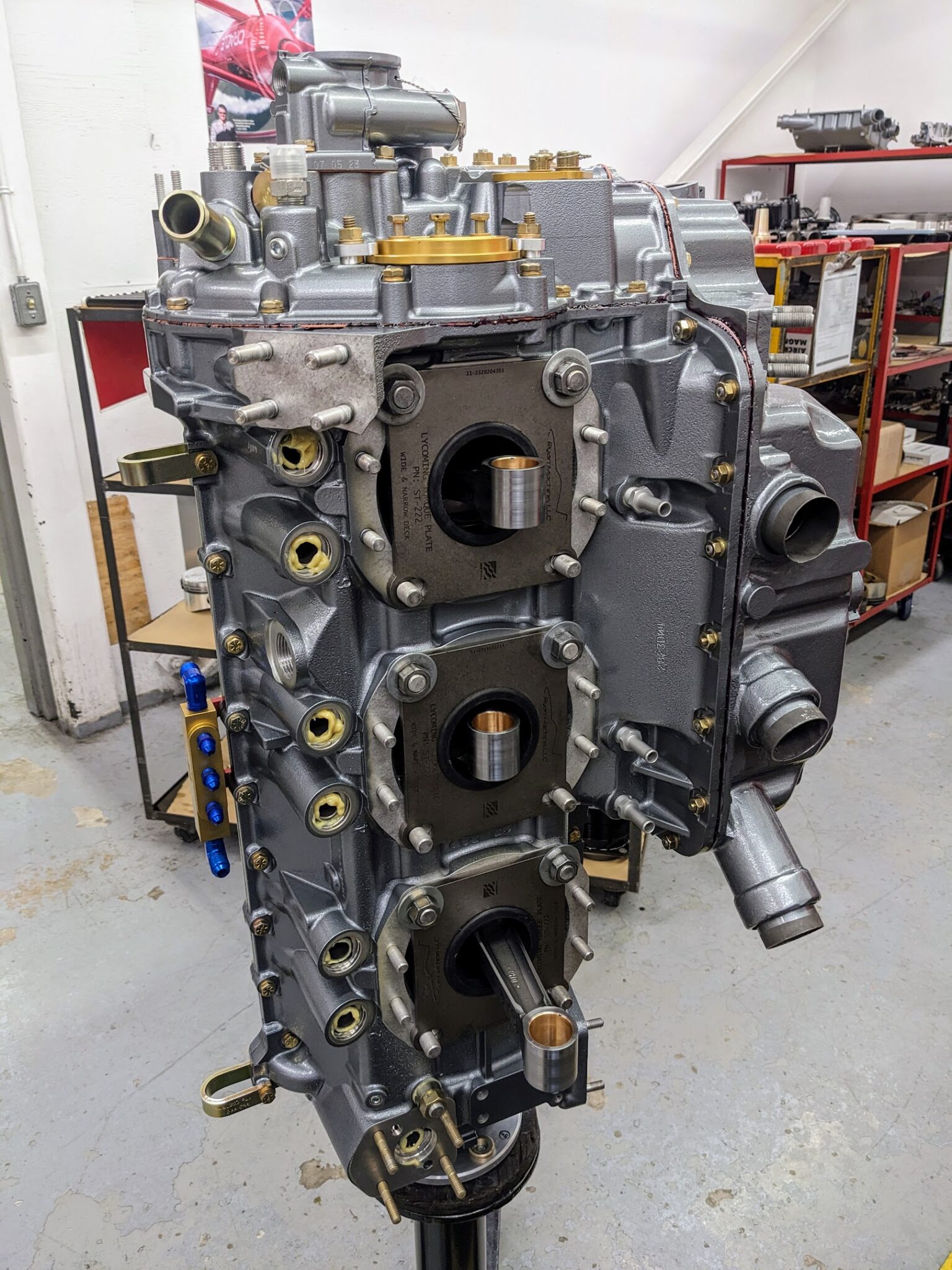
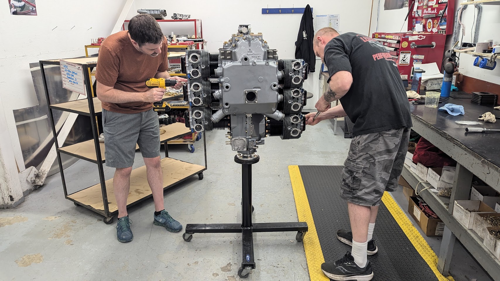
The engine is then mounted vertically on the rolling cart for the rest of the assembly.
The accessory components are installed next.
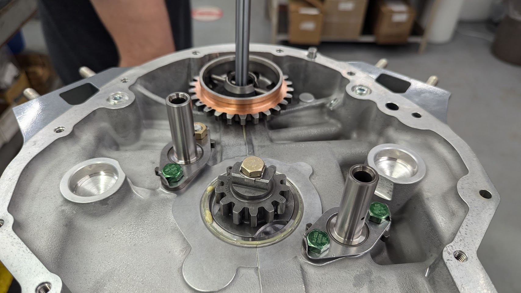
The gears are inserted and clocked.
Everything is coated in more grease and the accessory housing is installed. A gasket with gasket sealant is used here.
The SDS-provided magneto coil pack mounts were then installed.
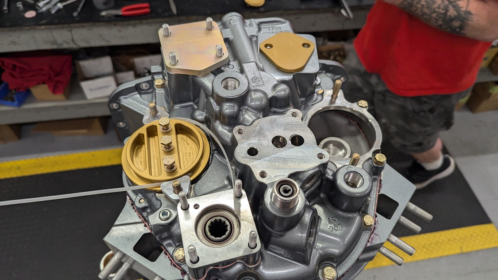
The spin-on oil filter adaptor is installed next. I chose to stick with a horizontal mount as I wanted to avoid additional hoses and fittings.
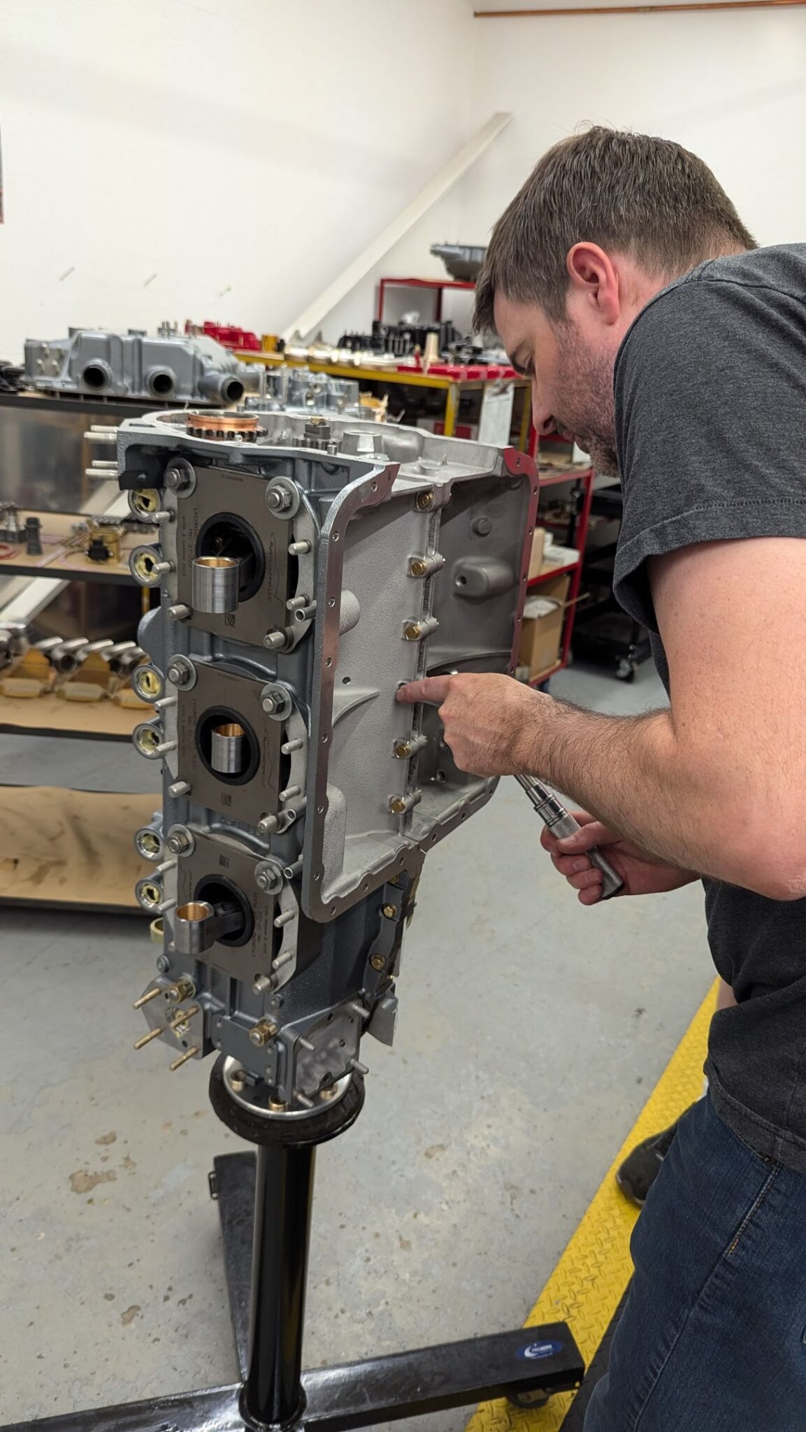
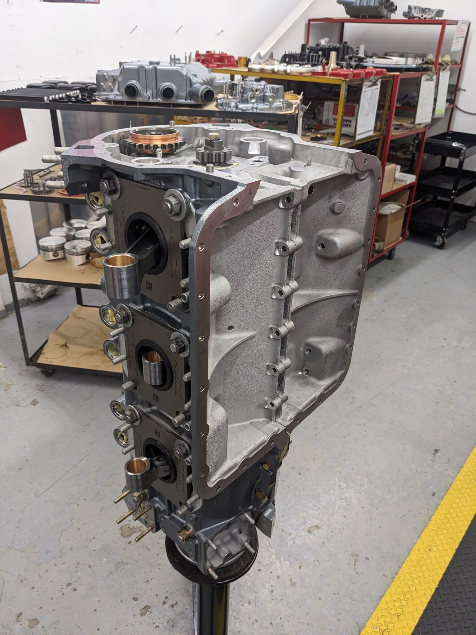
The oil sump is then installed using a gasket and more gasket sealant.
This completes day one of the build. We finished at around 3:30 pm.
Day 2
We were back at it at 7 am the next morning.
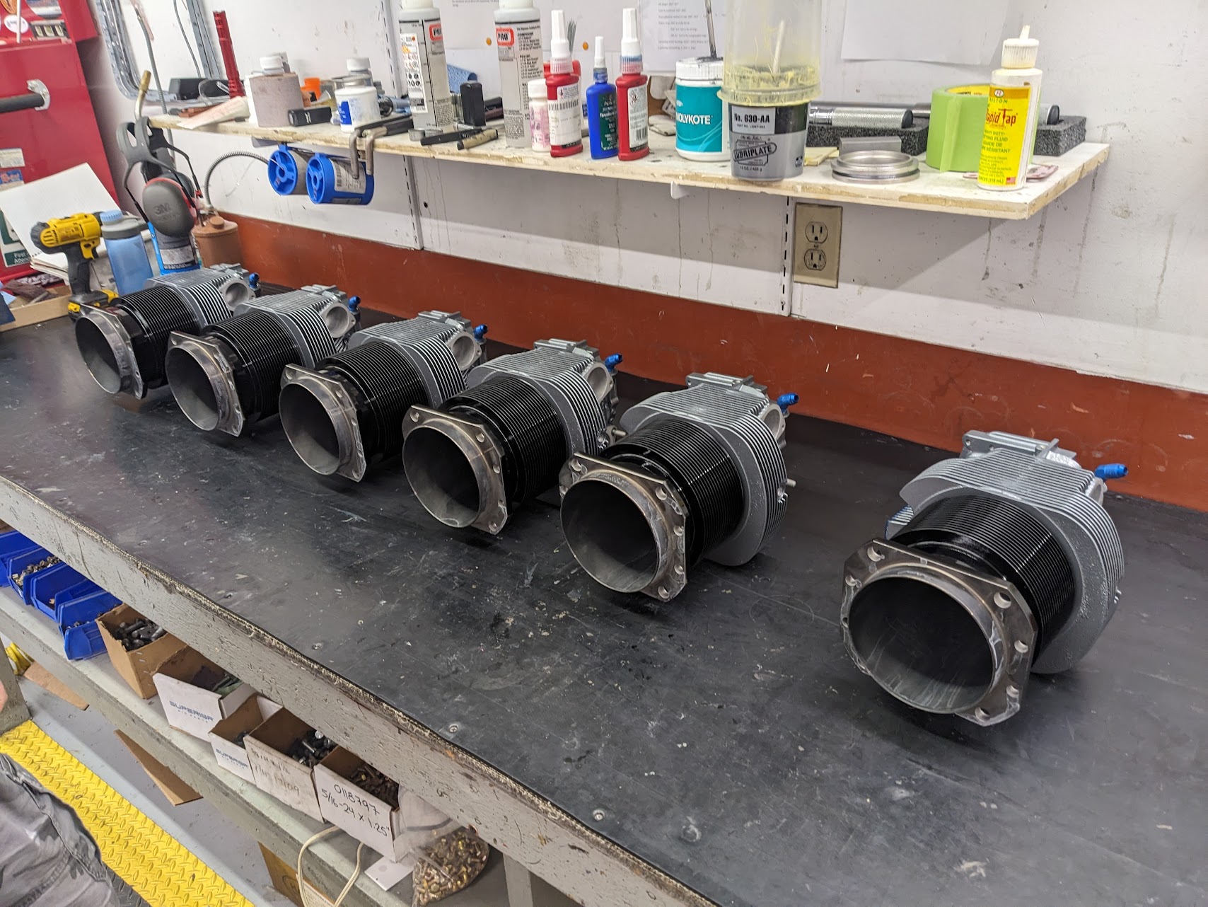
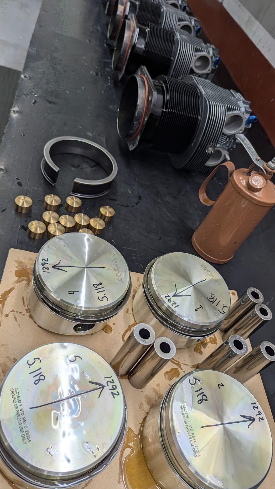
O-rings are installed on the cylinders.
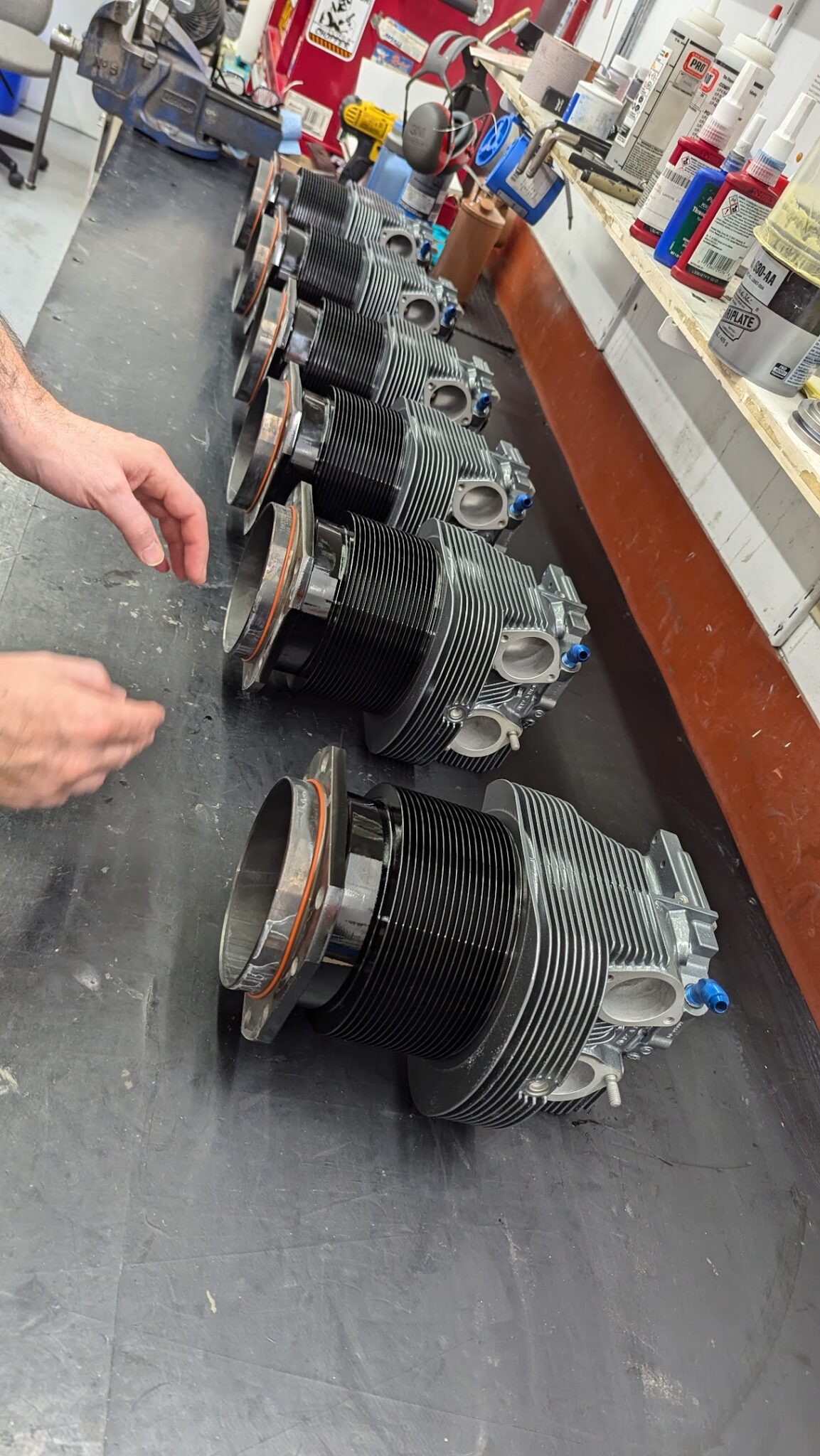
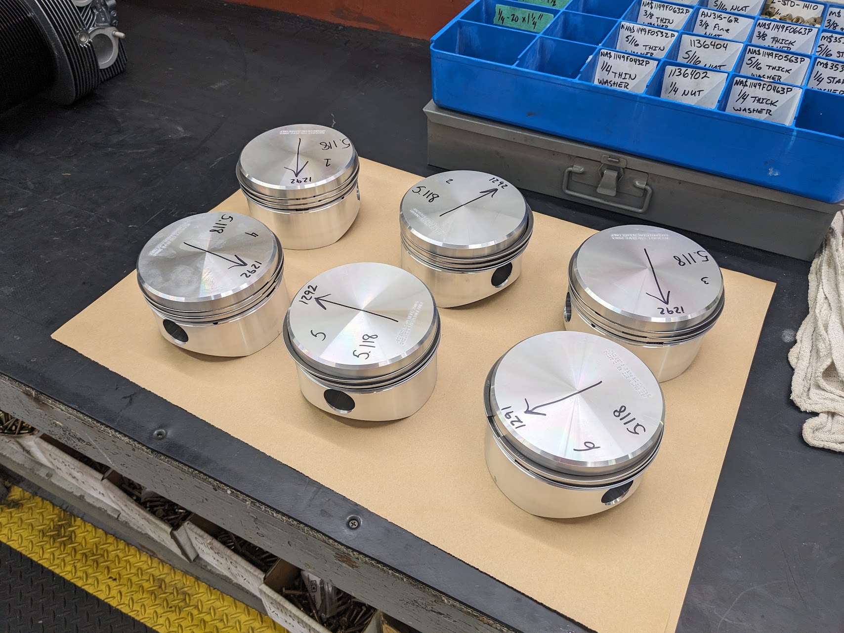
The pistons have been matched with the cylinders and tolerances have been checked. All are marked for installation.
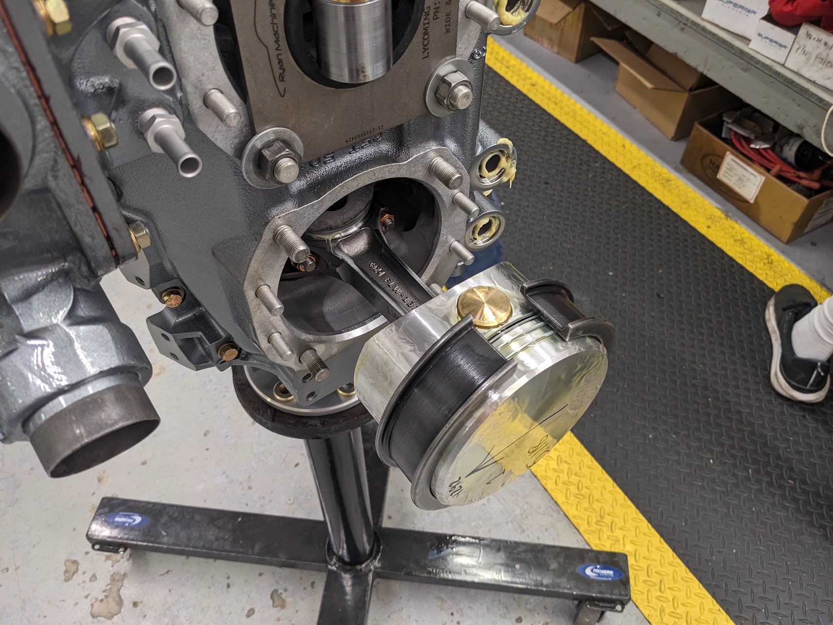
The piston rings are adjusted to distribute the gaps in thirds around the piston (so that the gaps do not align). A tool is used to compress the rings, allowing the cylinder to slide over the rings. The pistons are coated in oil before install.
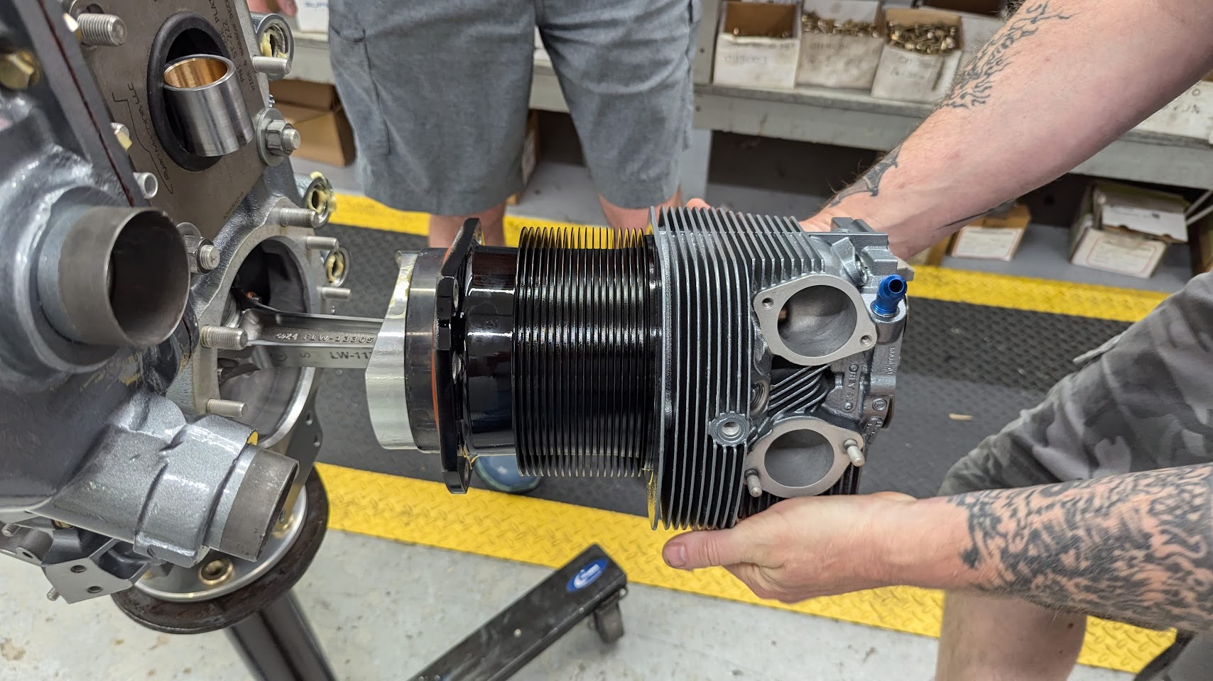
It starts to really look like an engine at this stage of the build.
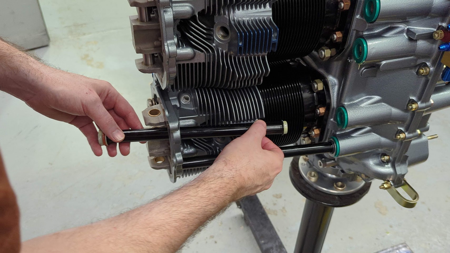
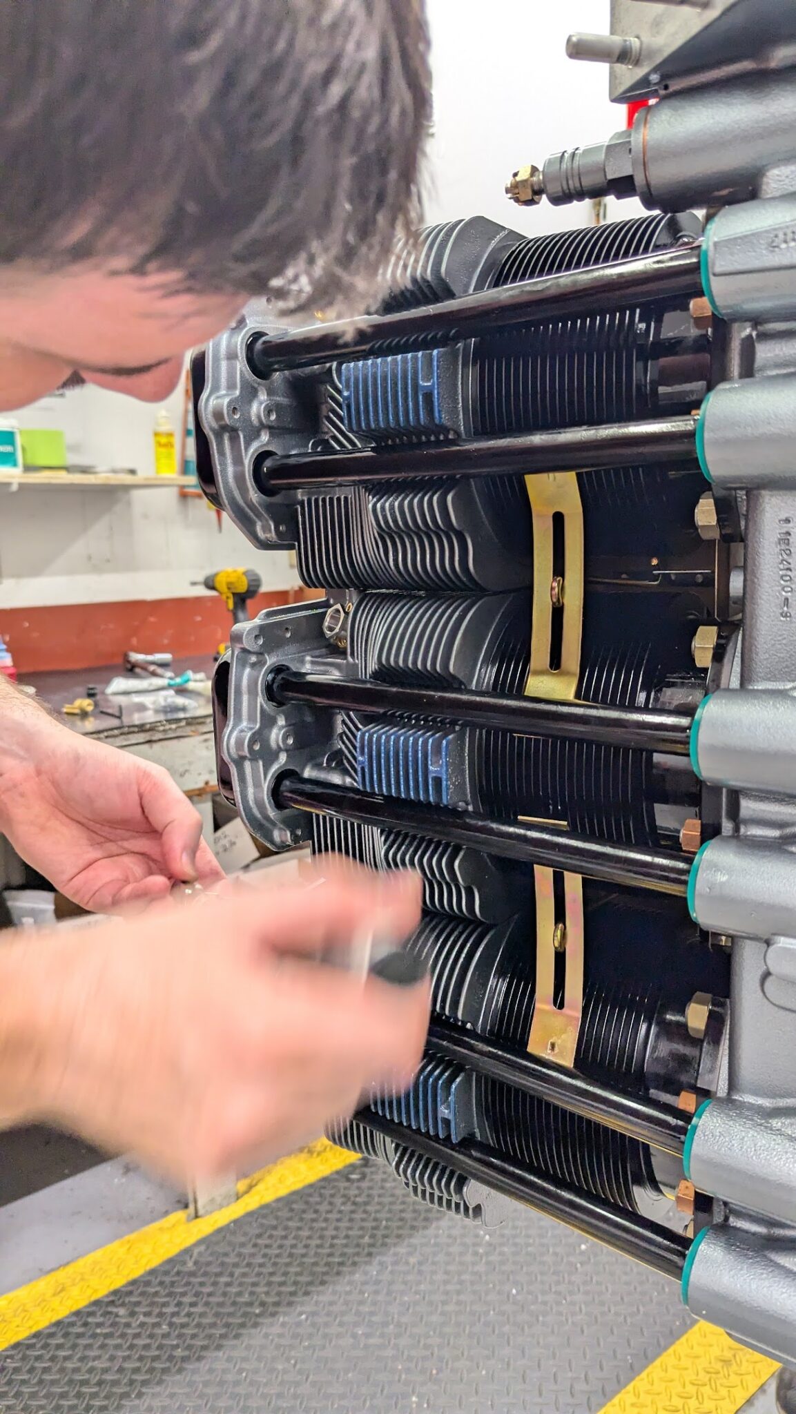
The push rod sockets are then installed, followed by the push rod shrouds, push rods, and the valve rockers.
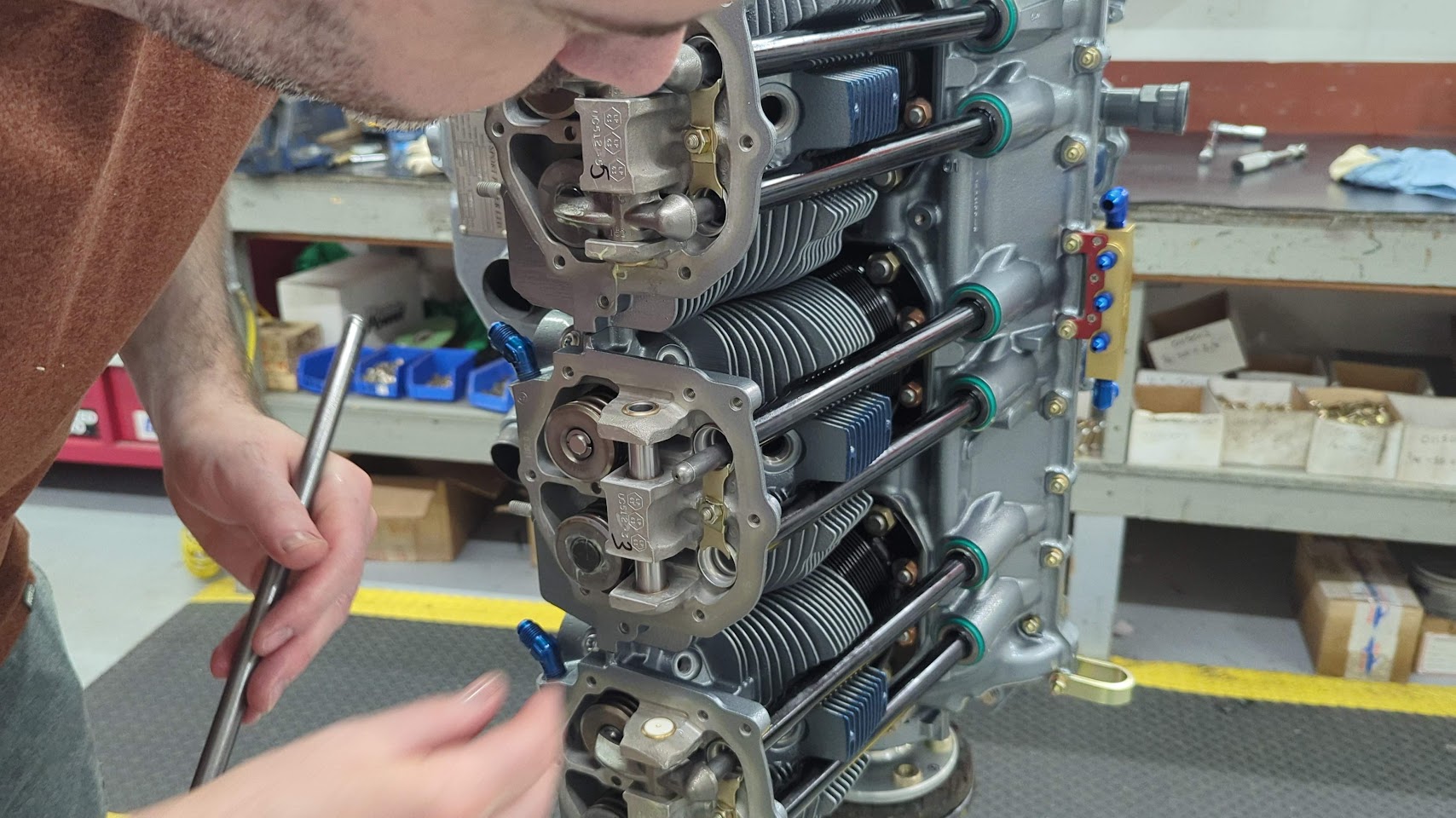
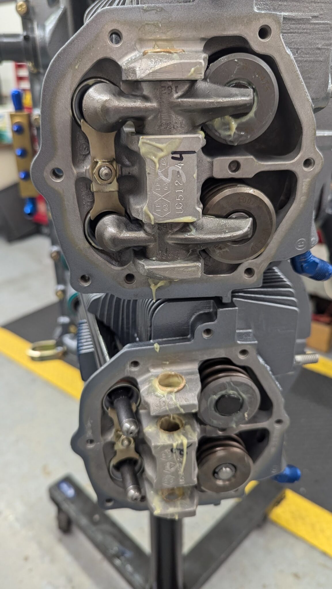
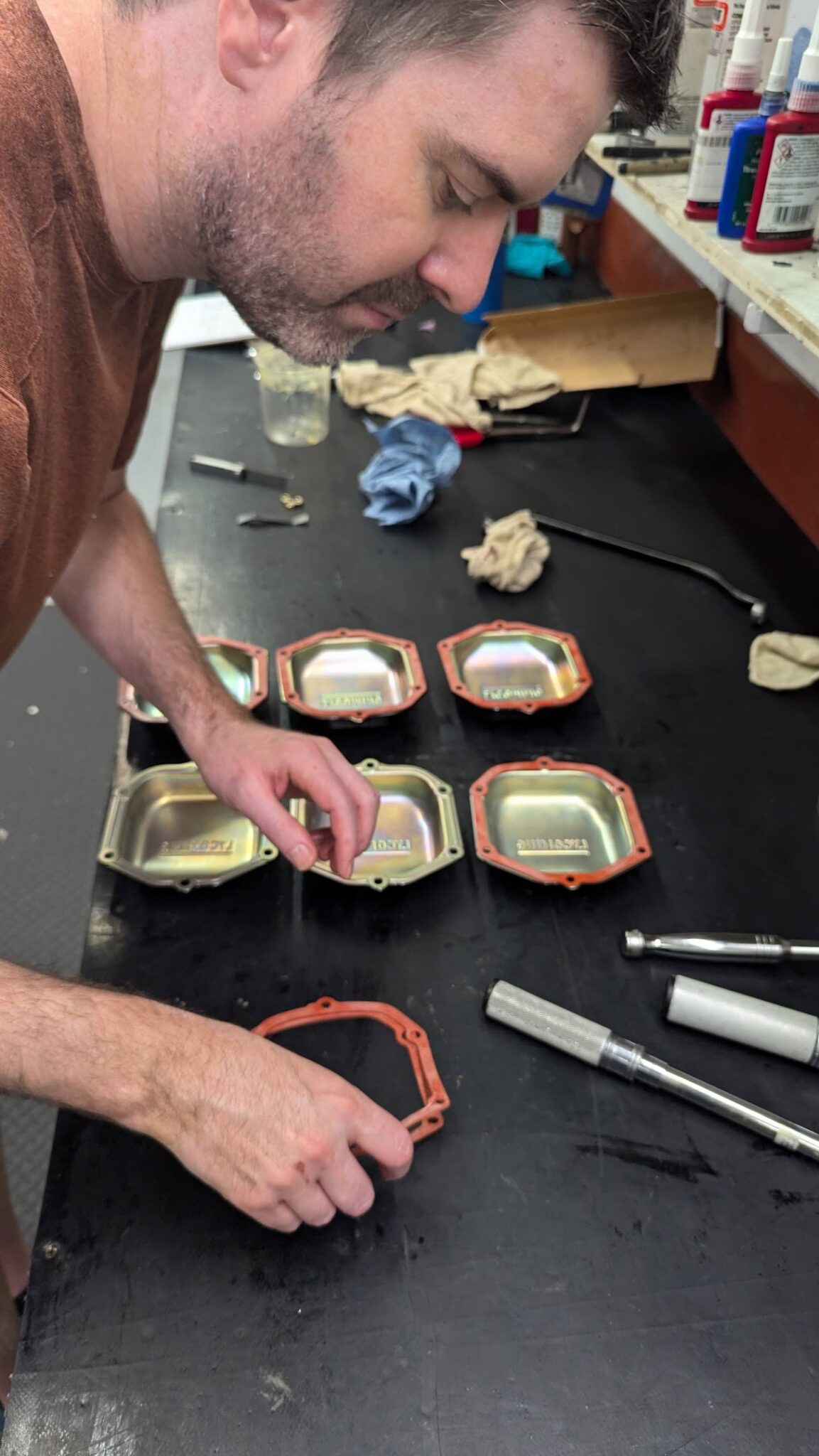
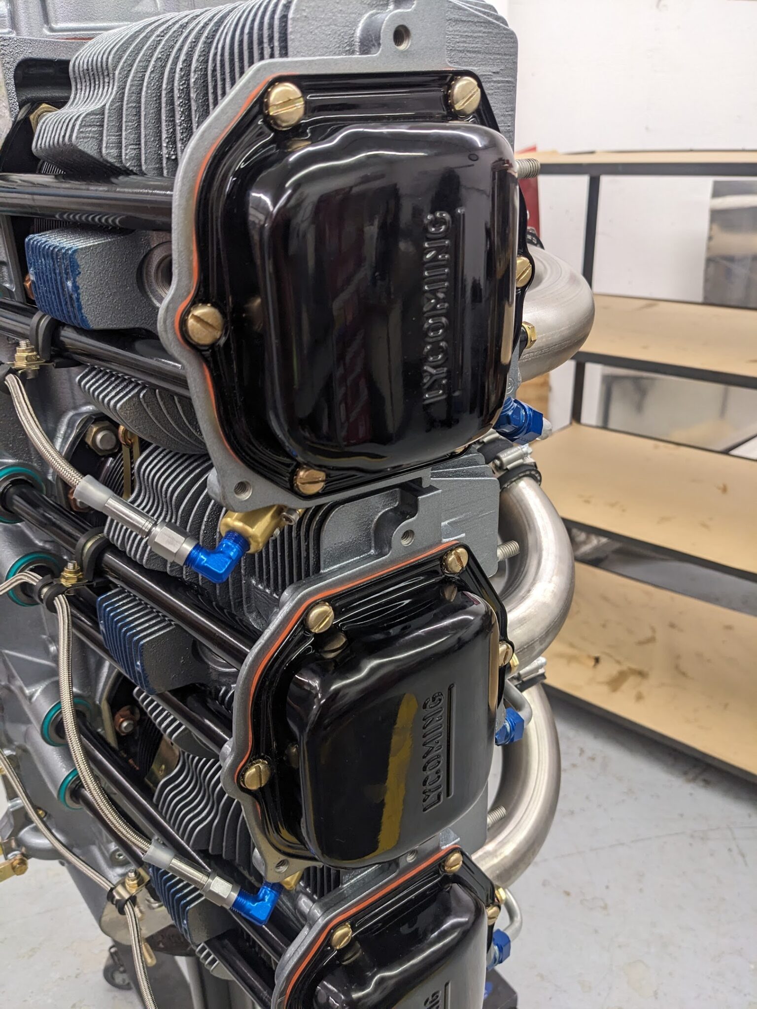
The valve covers are then installed.
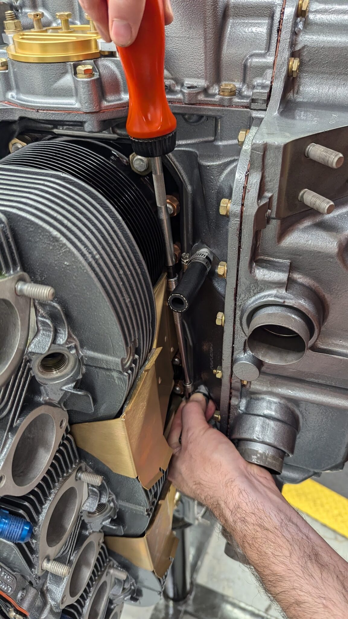
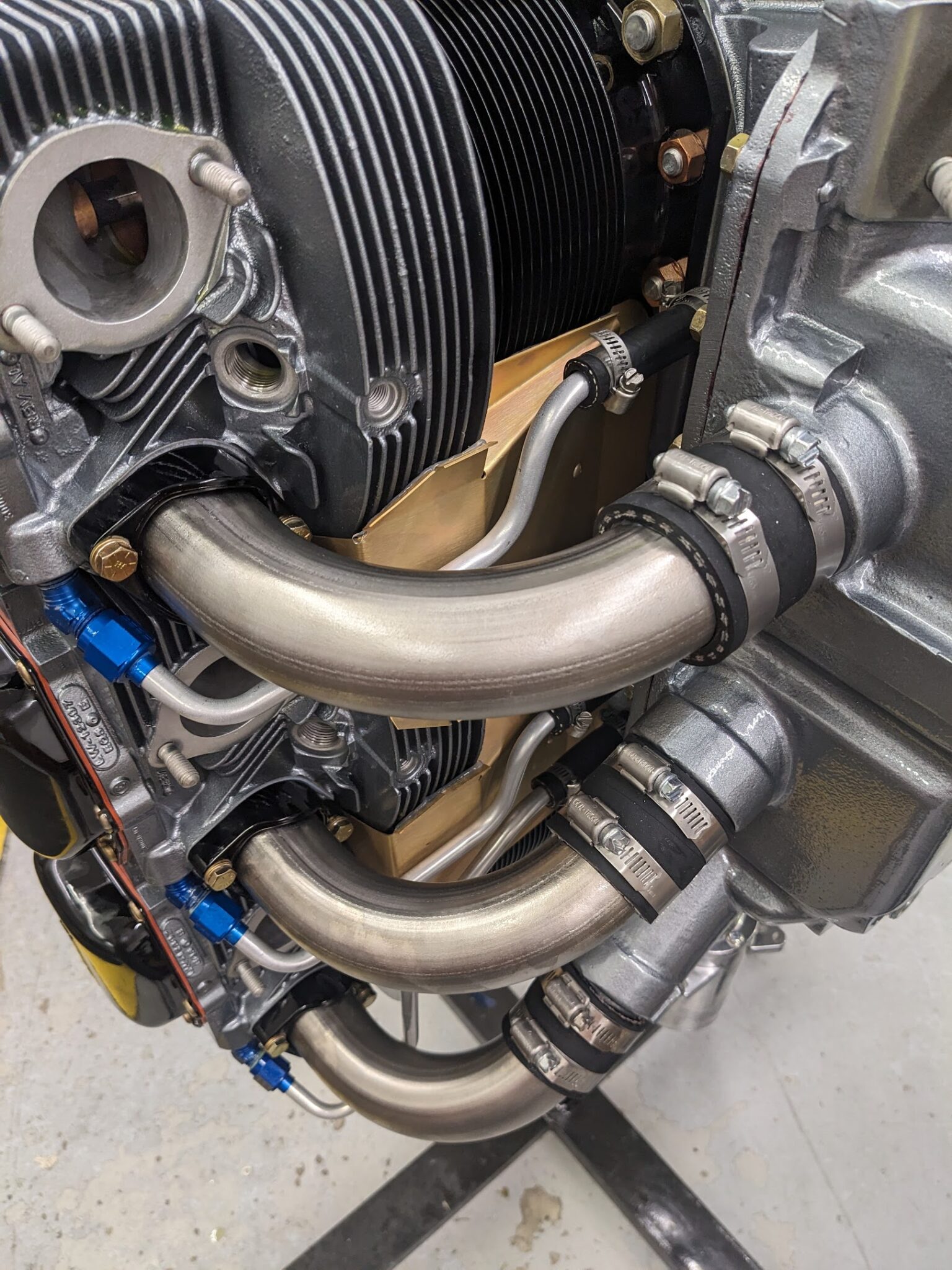
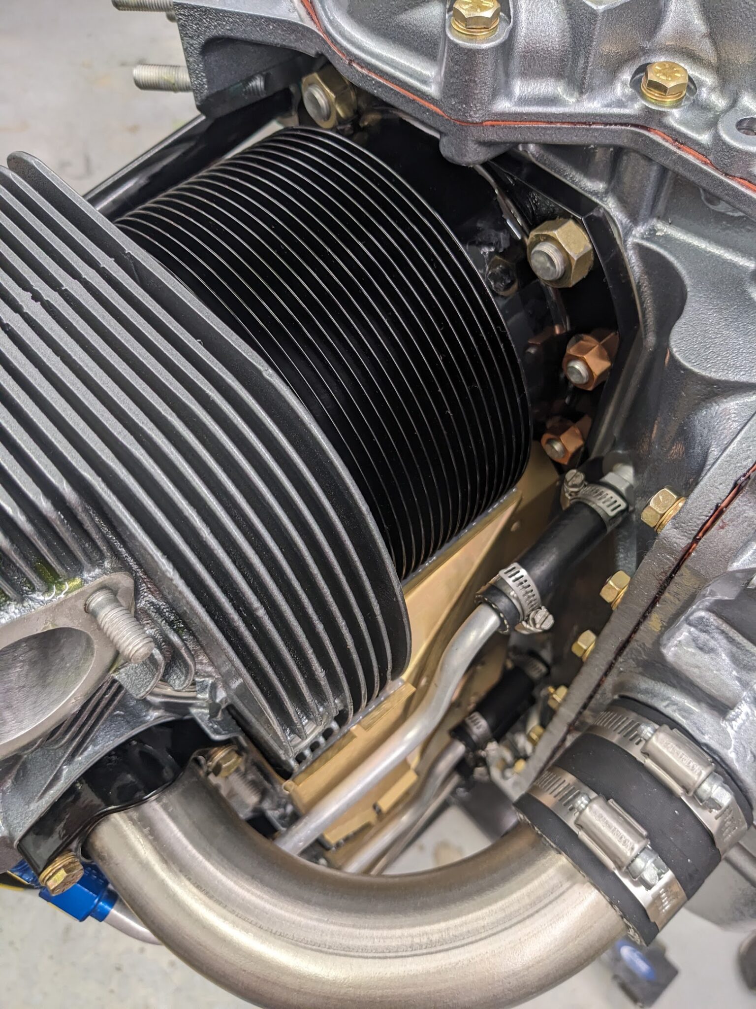
The intercylinder cooling baffles are then installed.
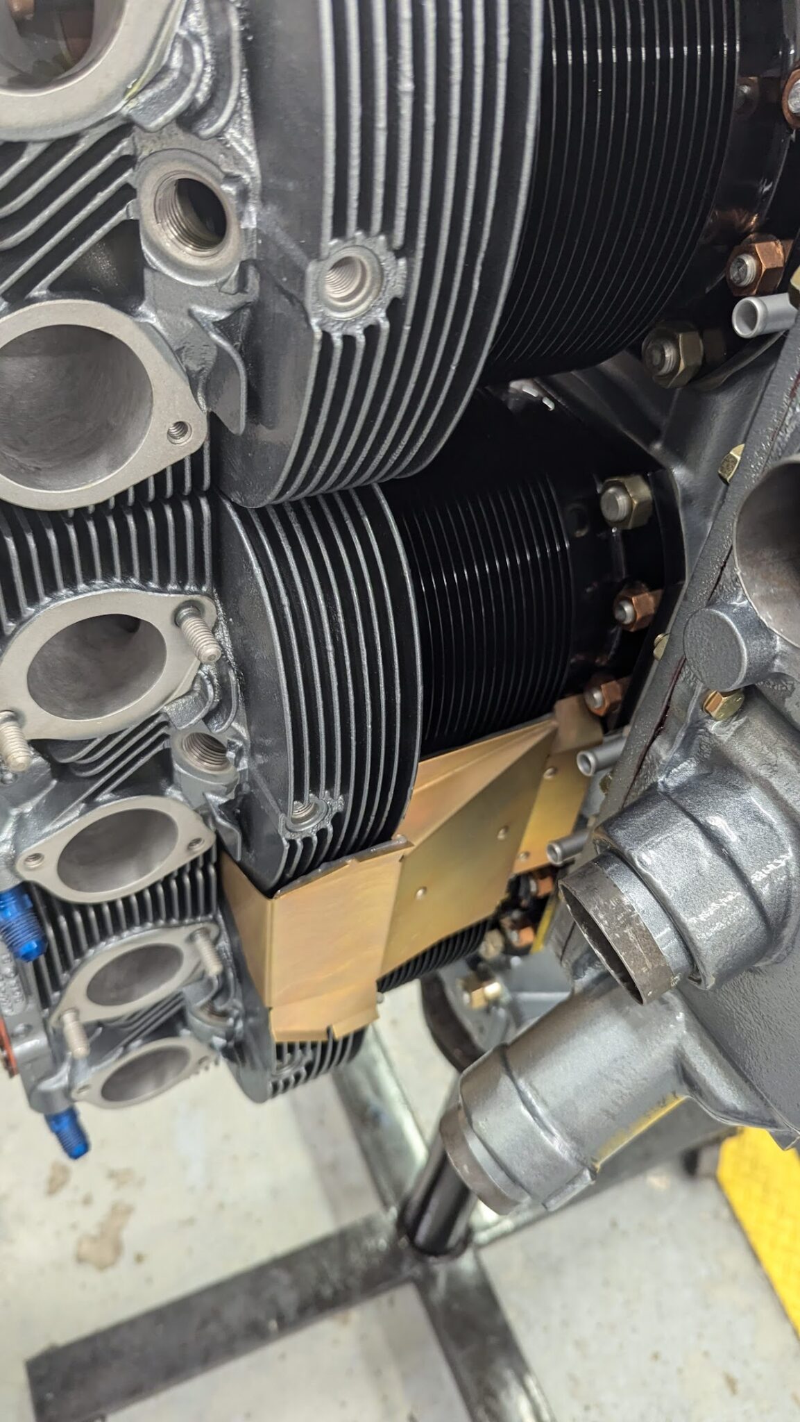
This is followed by the installation of the cylinder head drain tubes.
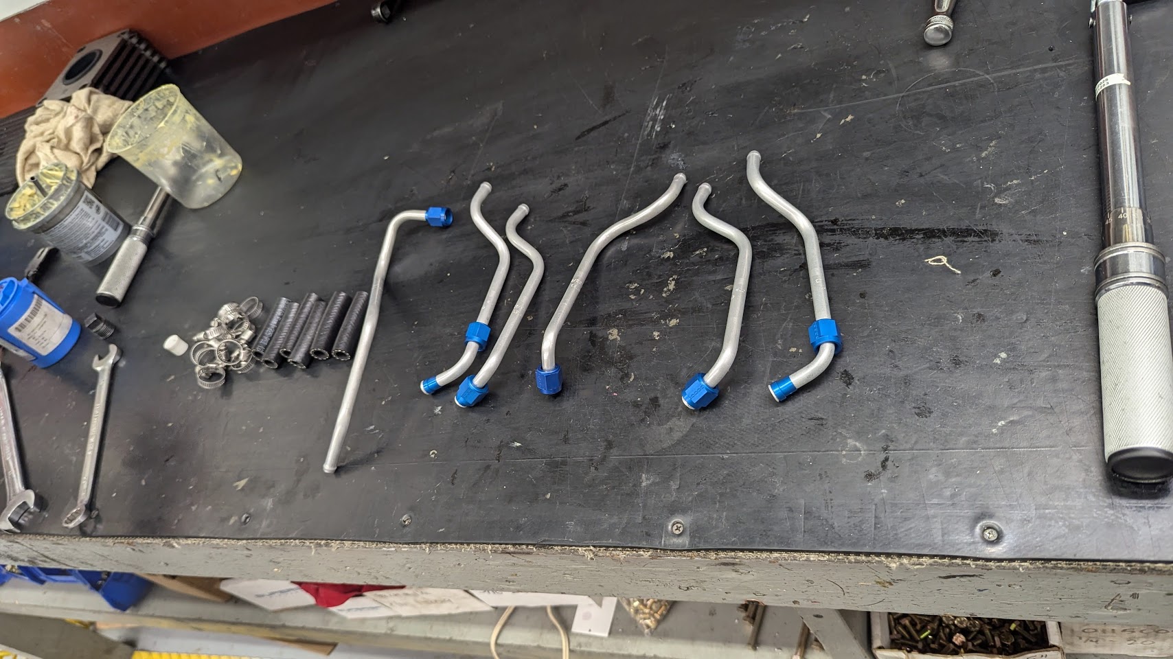
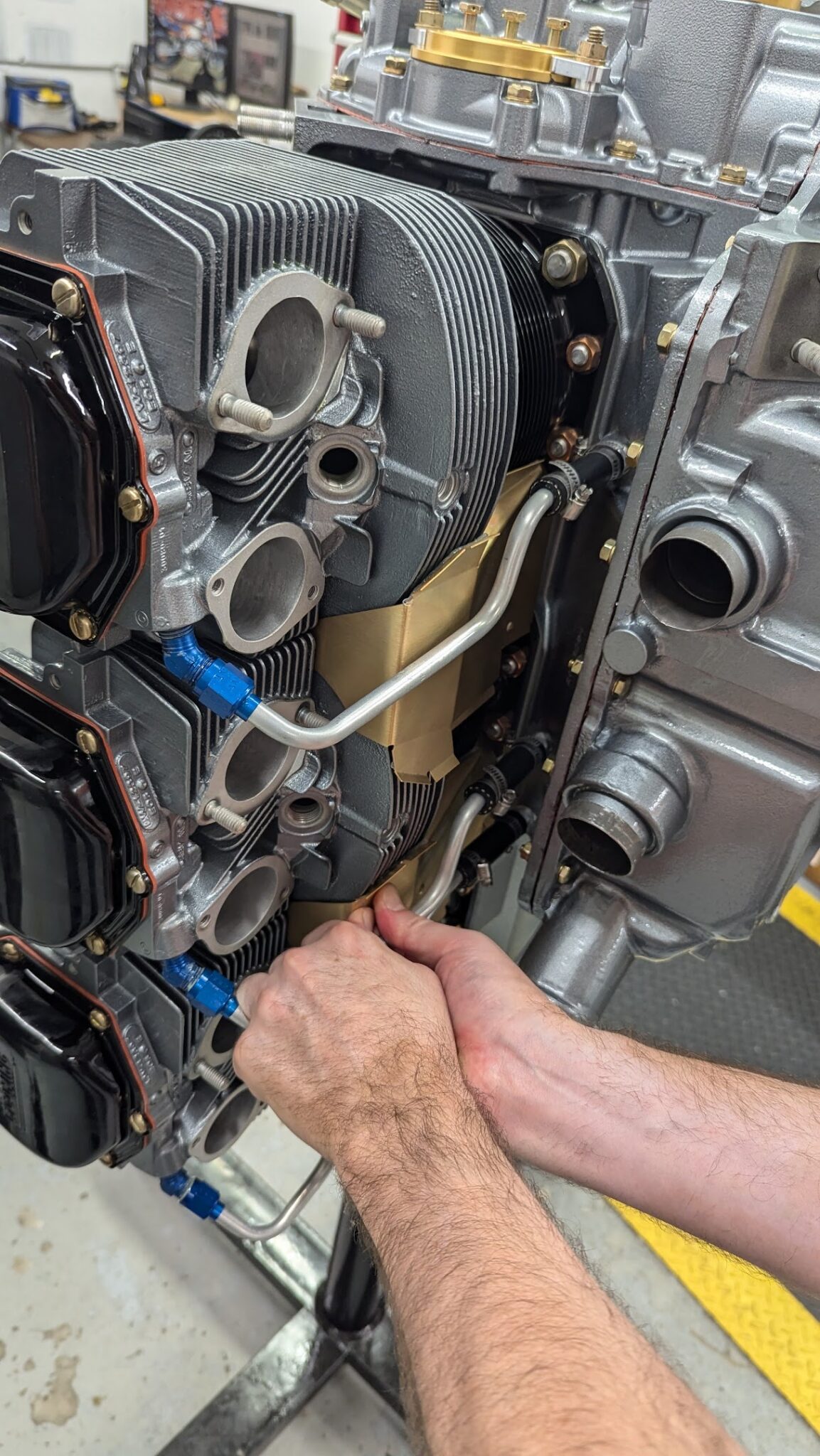
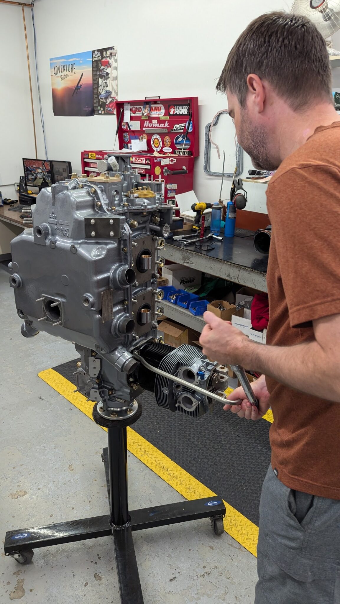
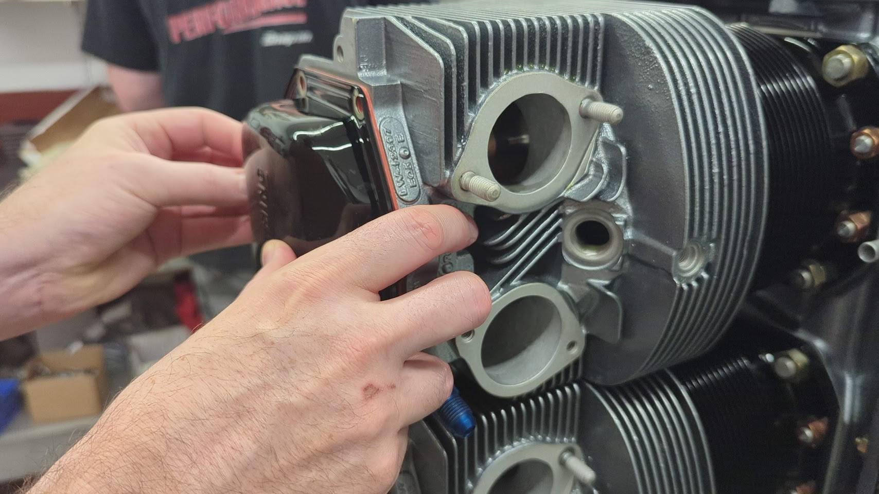
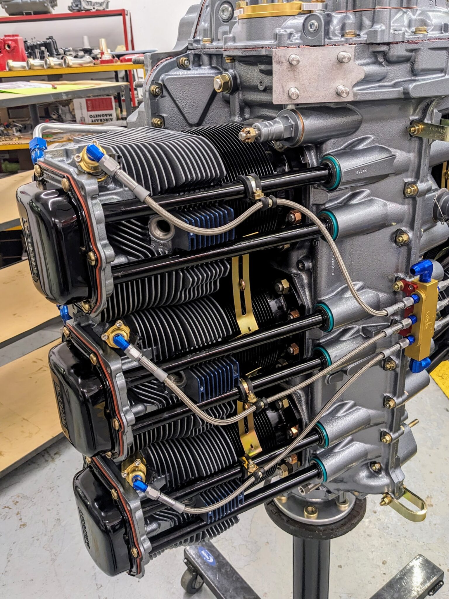
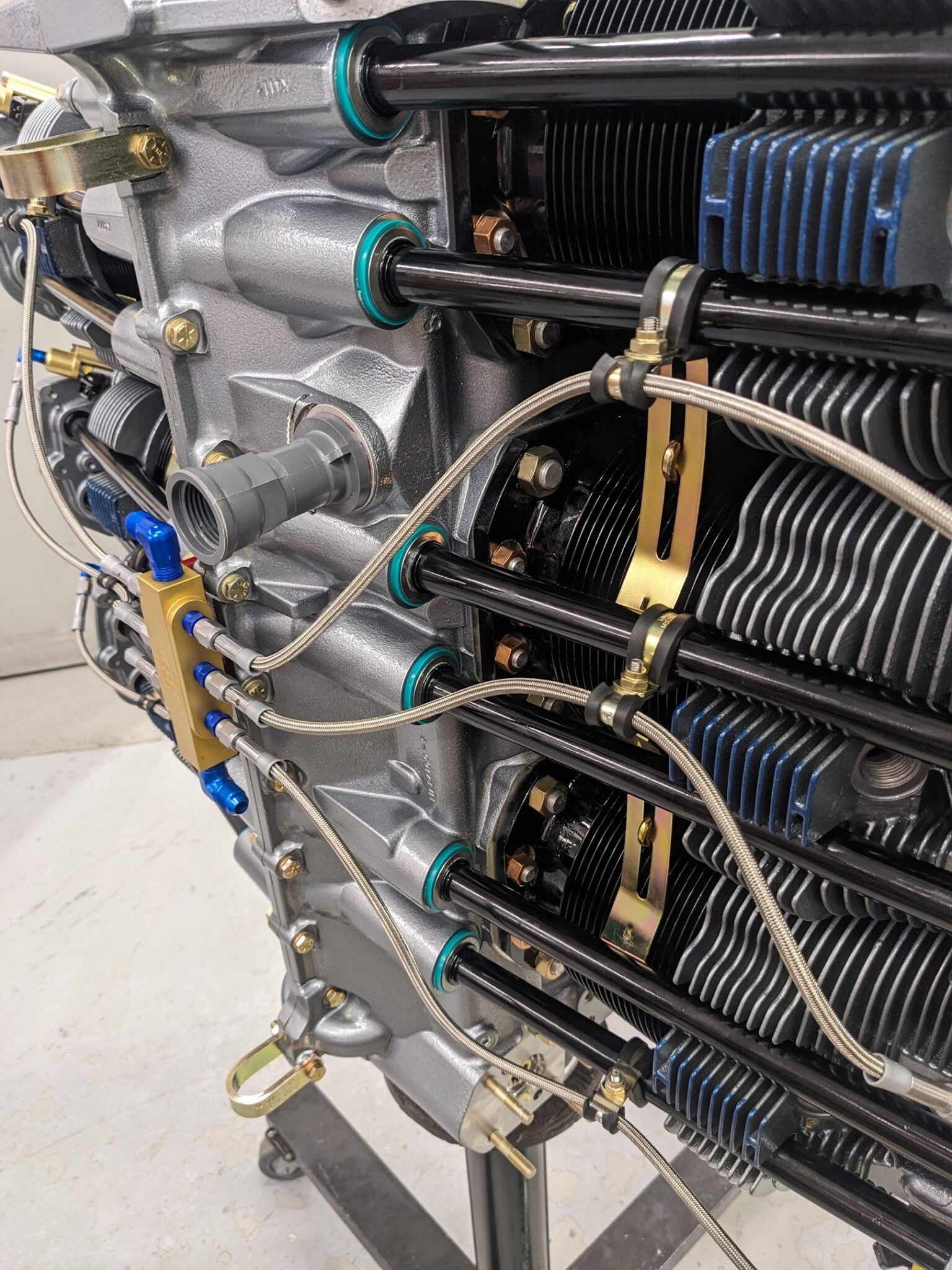
Next up, the intake tubes are installed.
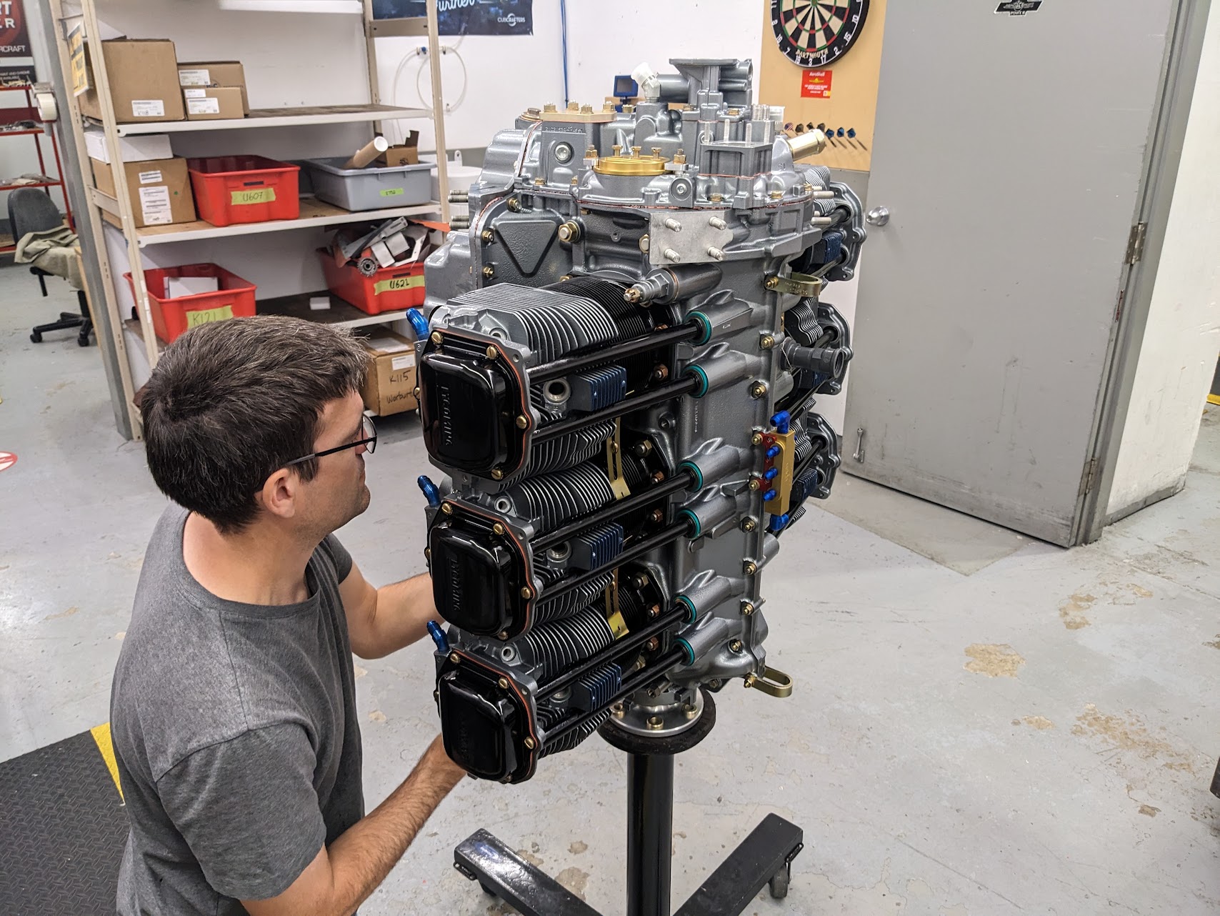
This is followed by the installation of the SDS fuel injectors. The SDS bosses mount the injectors into the original injector holes.
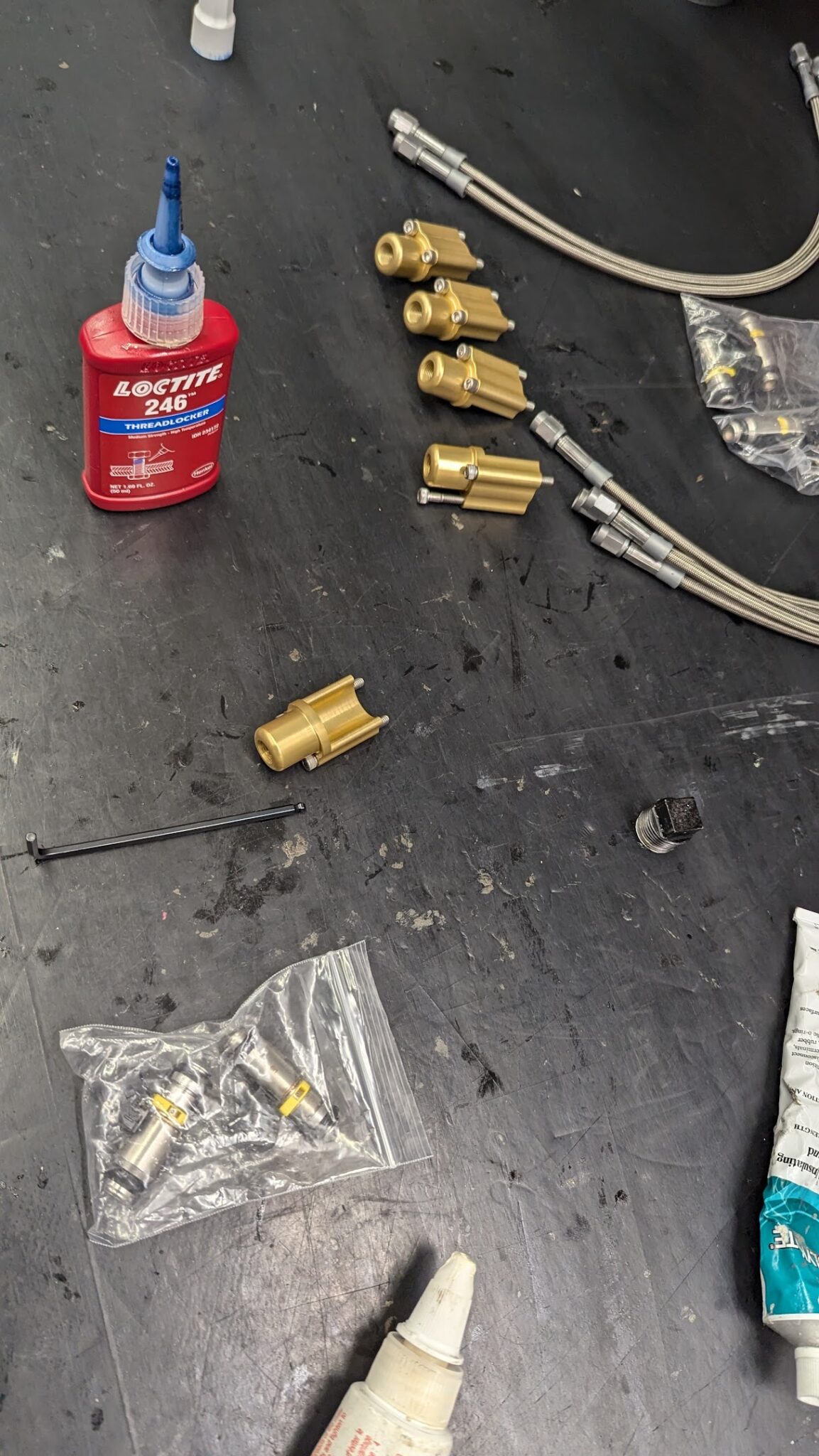
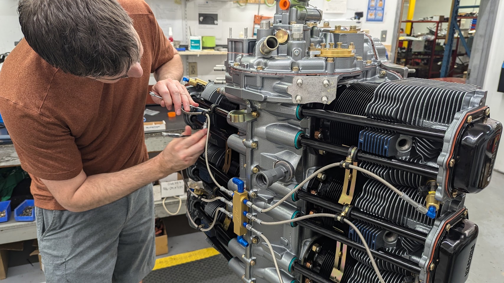
The fuel hoses from the center mount fuel block to the injectors are installed and secured with adel clamps to the push rod shrouds.
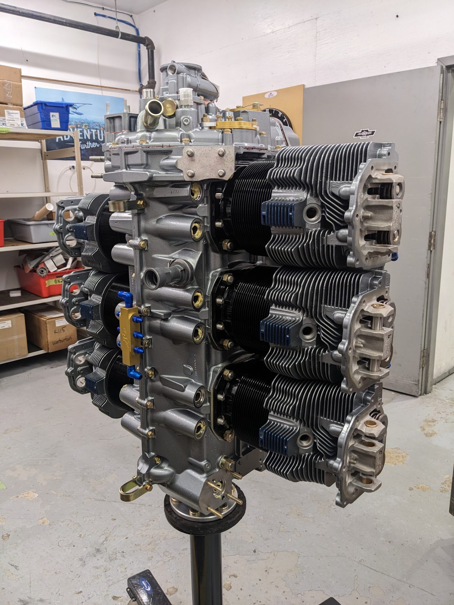
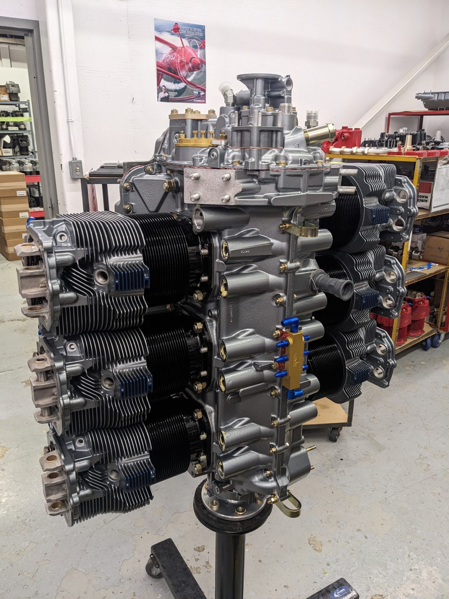
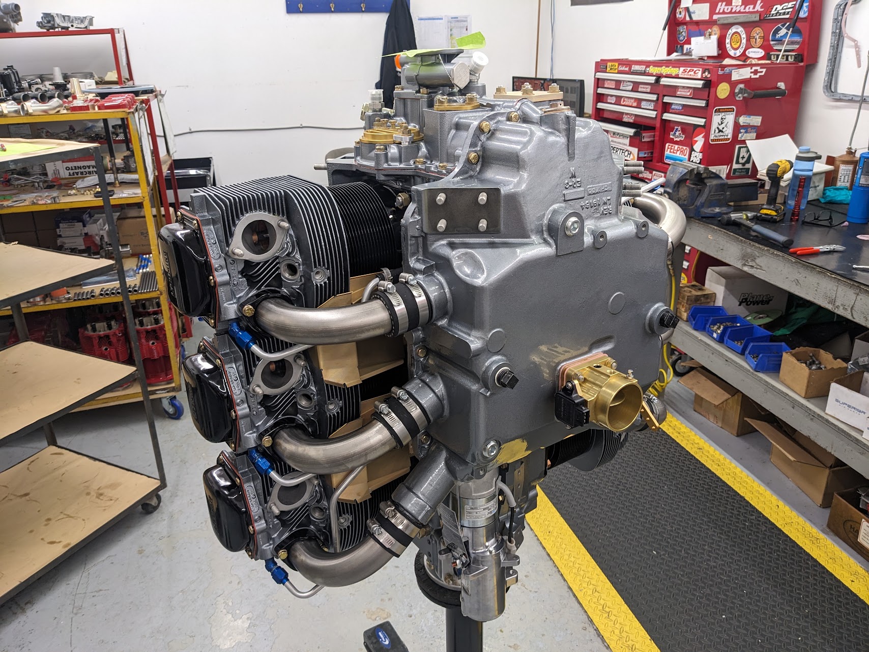
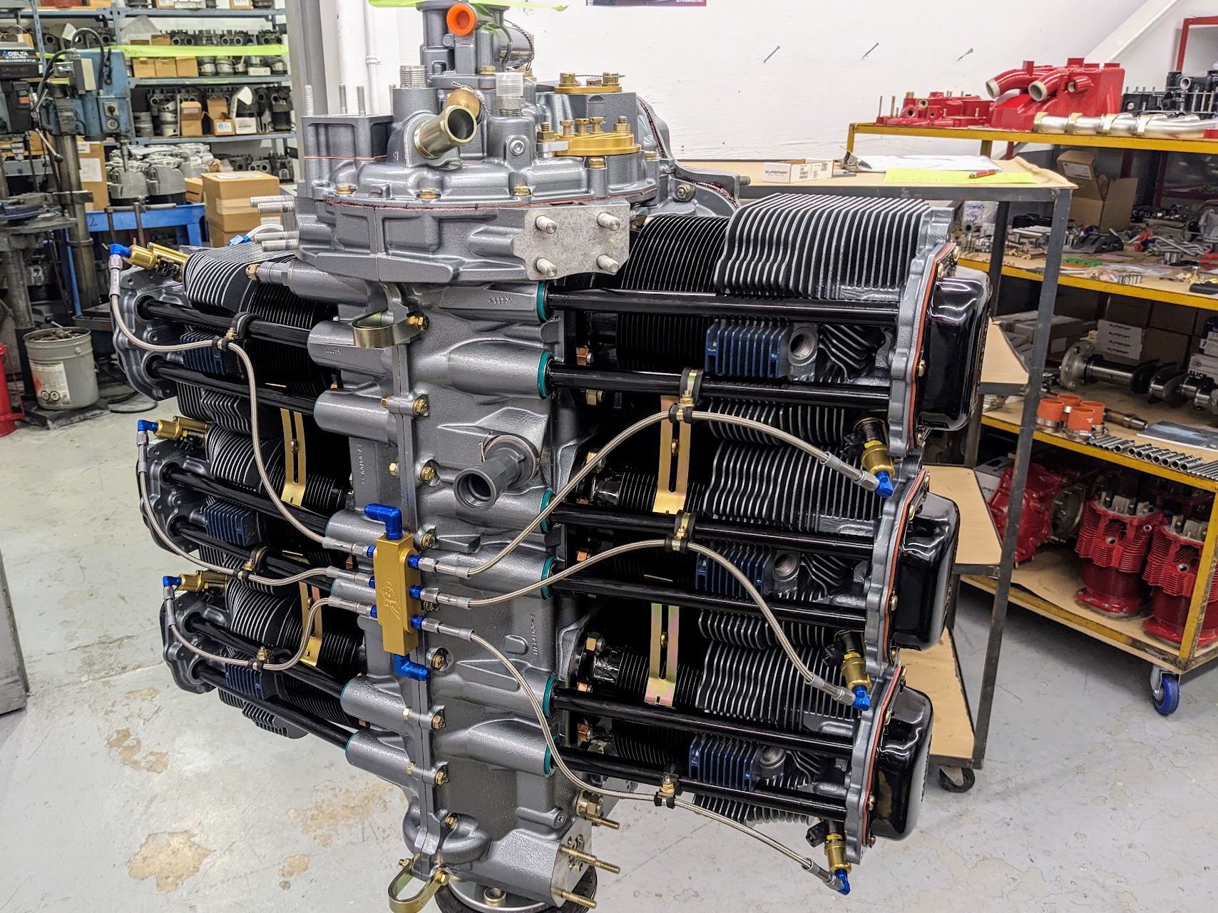
Finally, the SDS throttle body is mounted and the starter is installed.
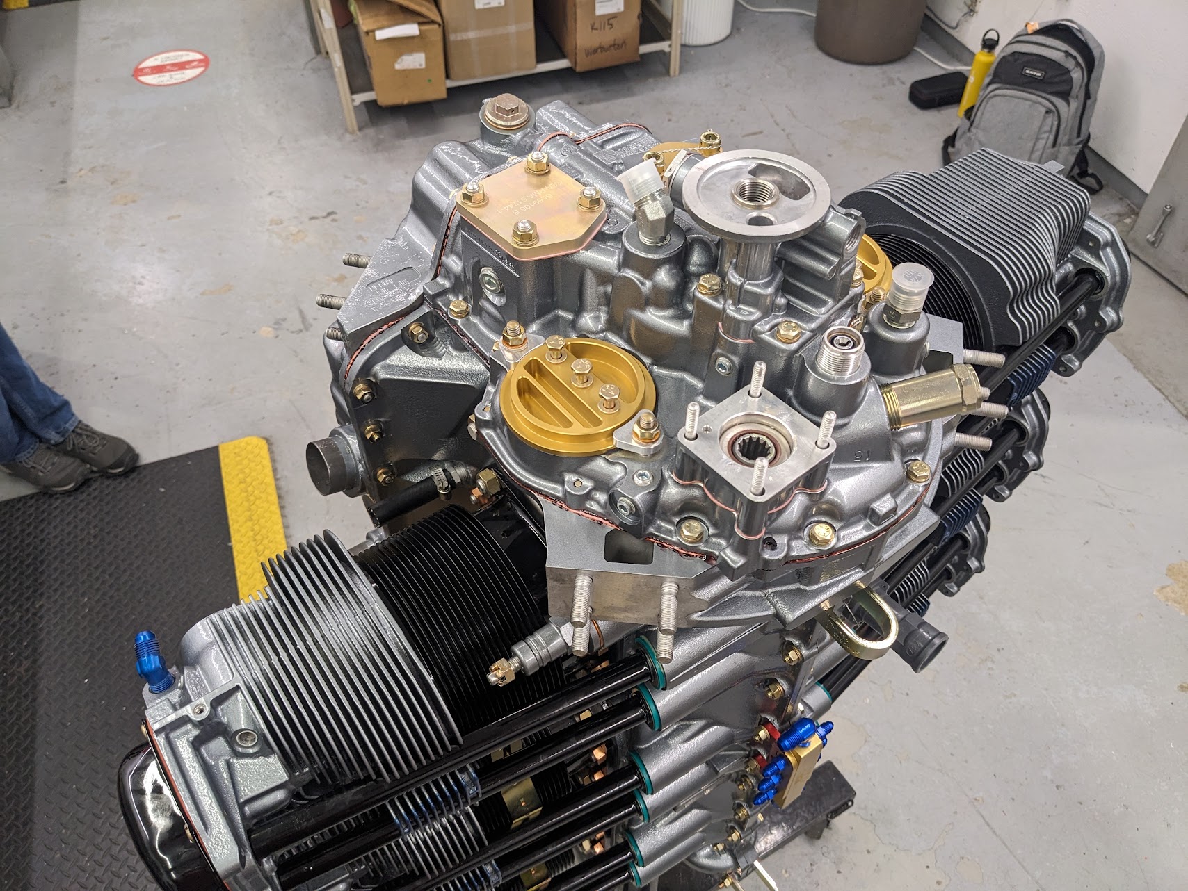
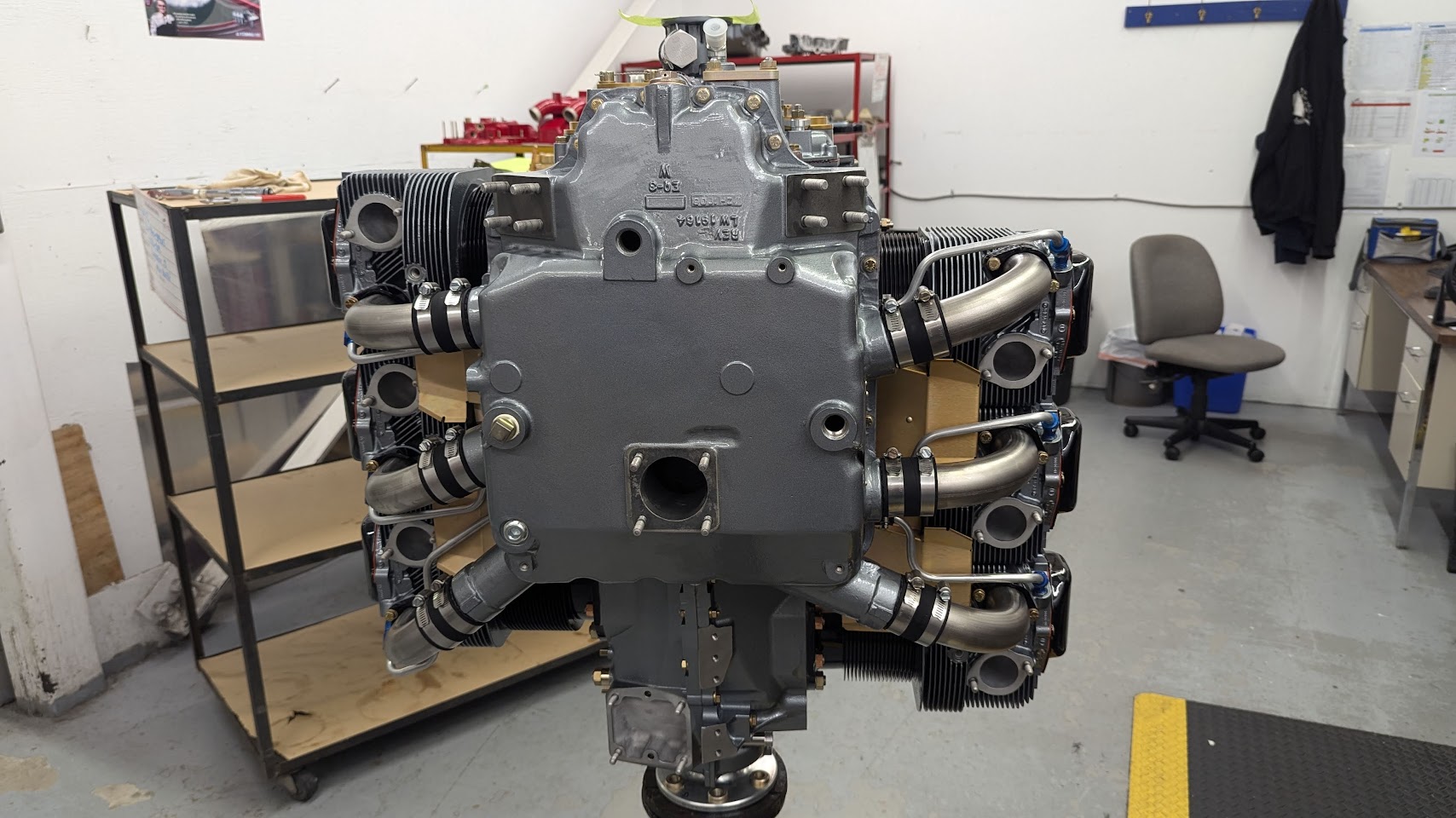
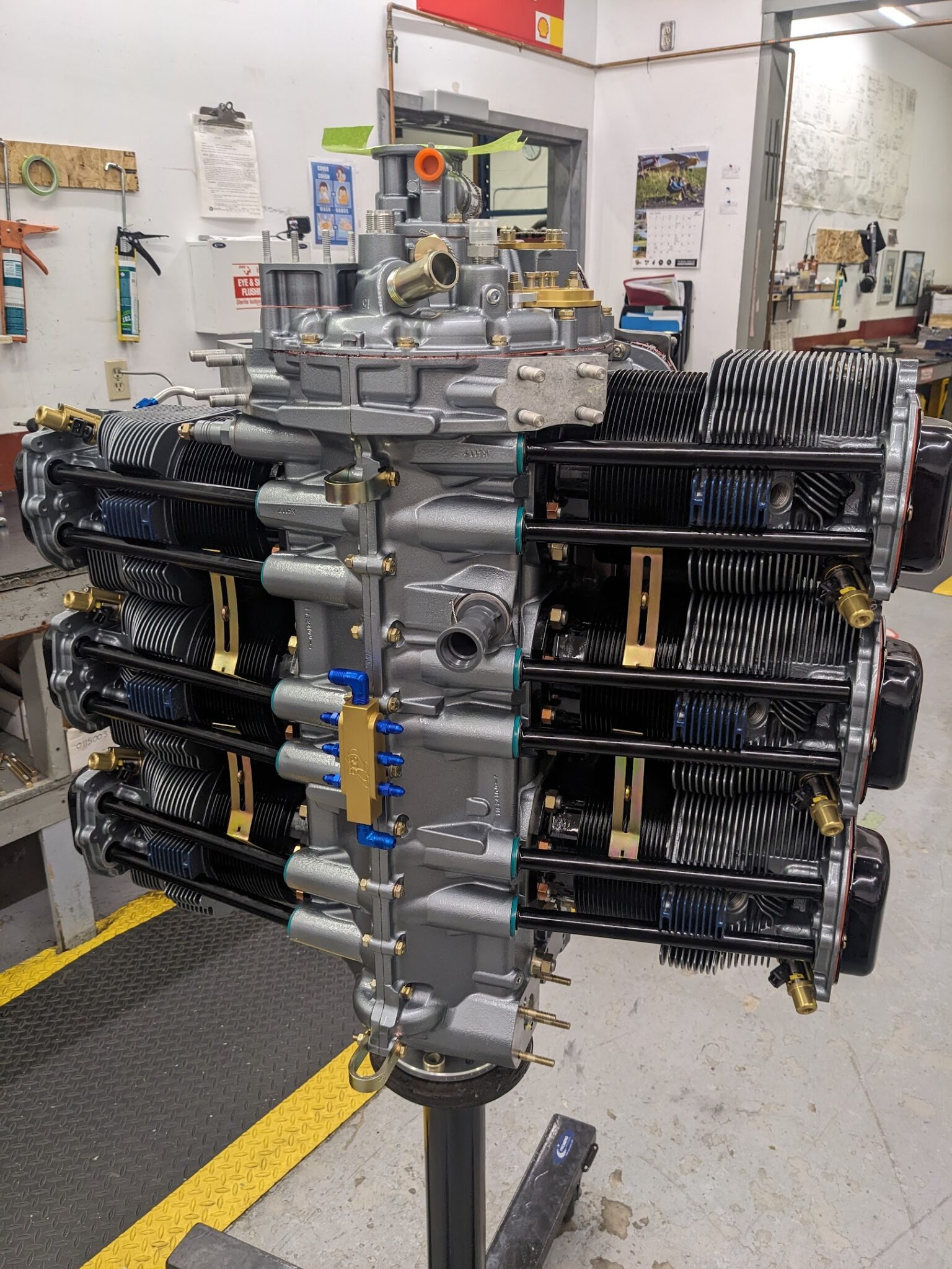
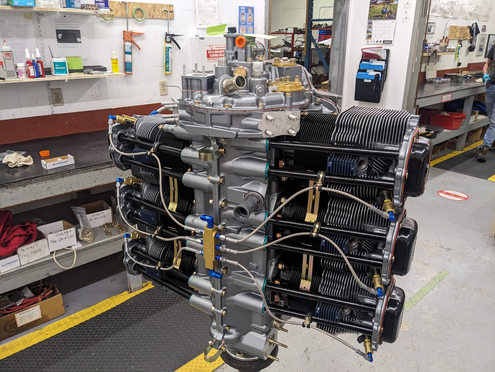
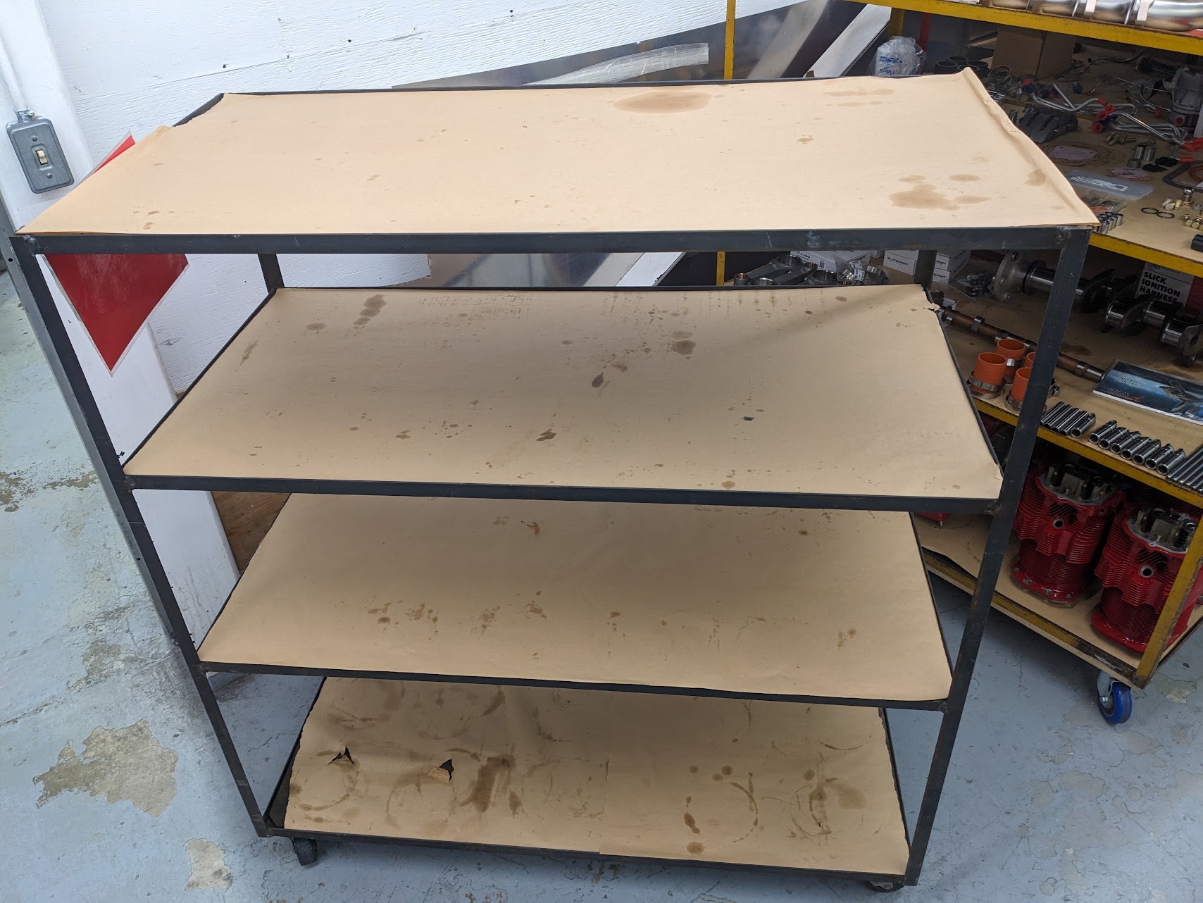
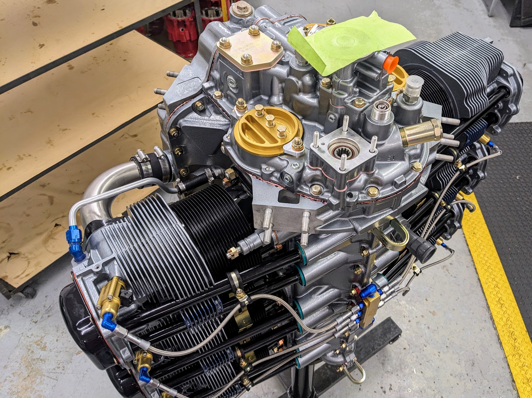
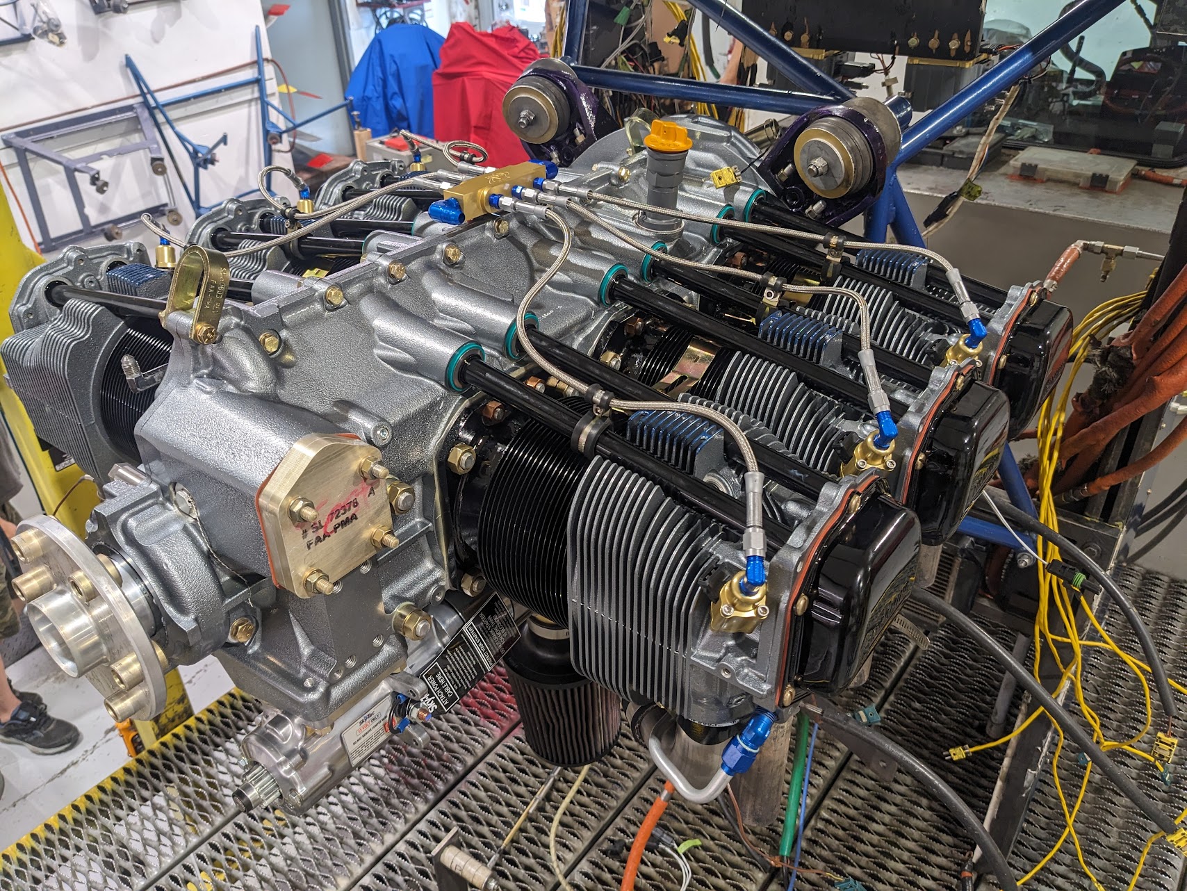
The parts shelf is empty…
and we have a fully assembled engine!
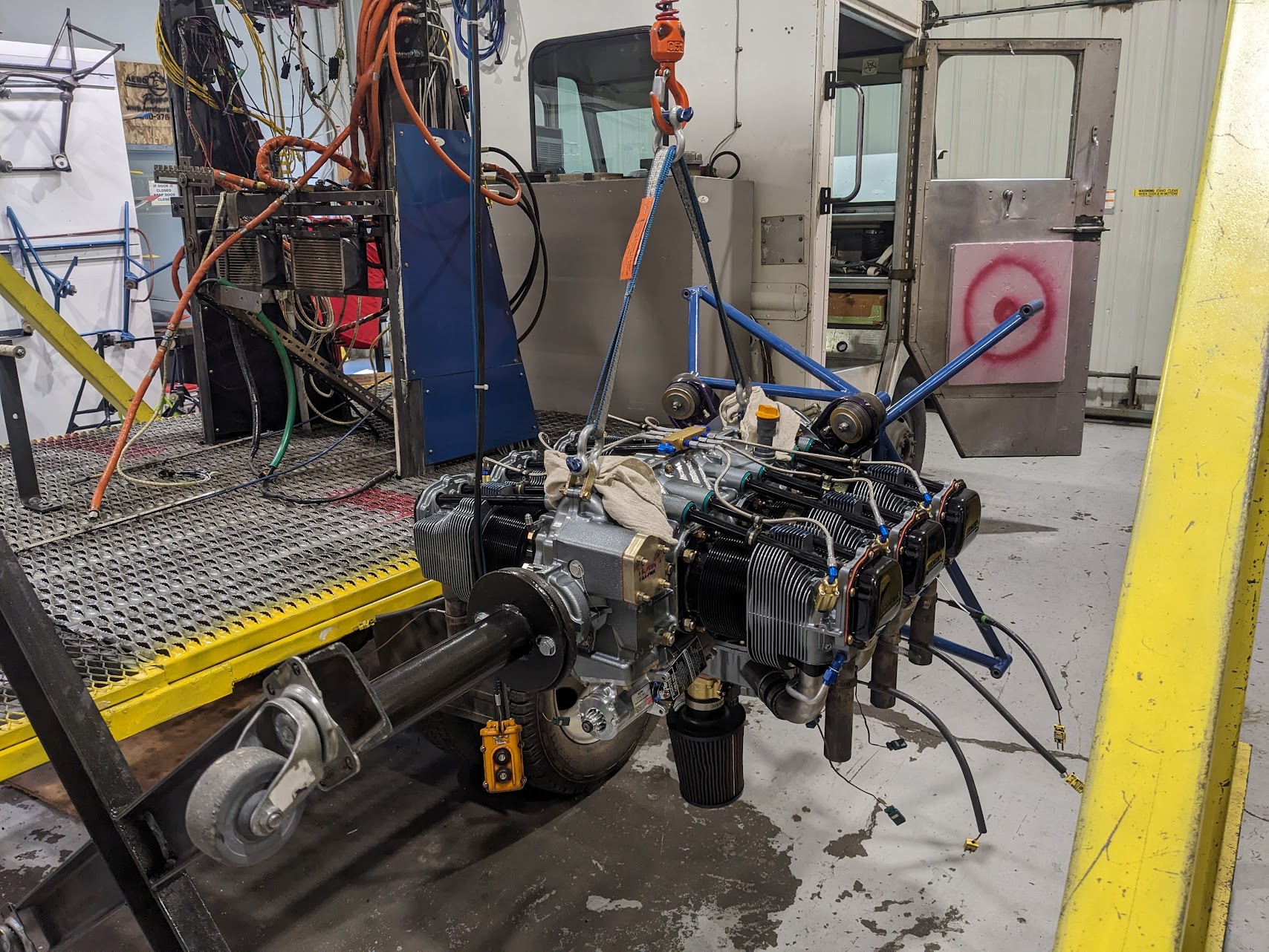
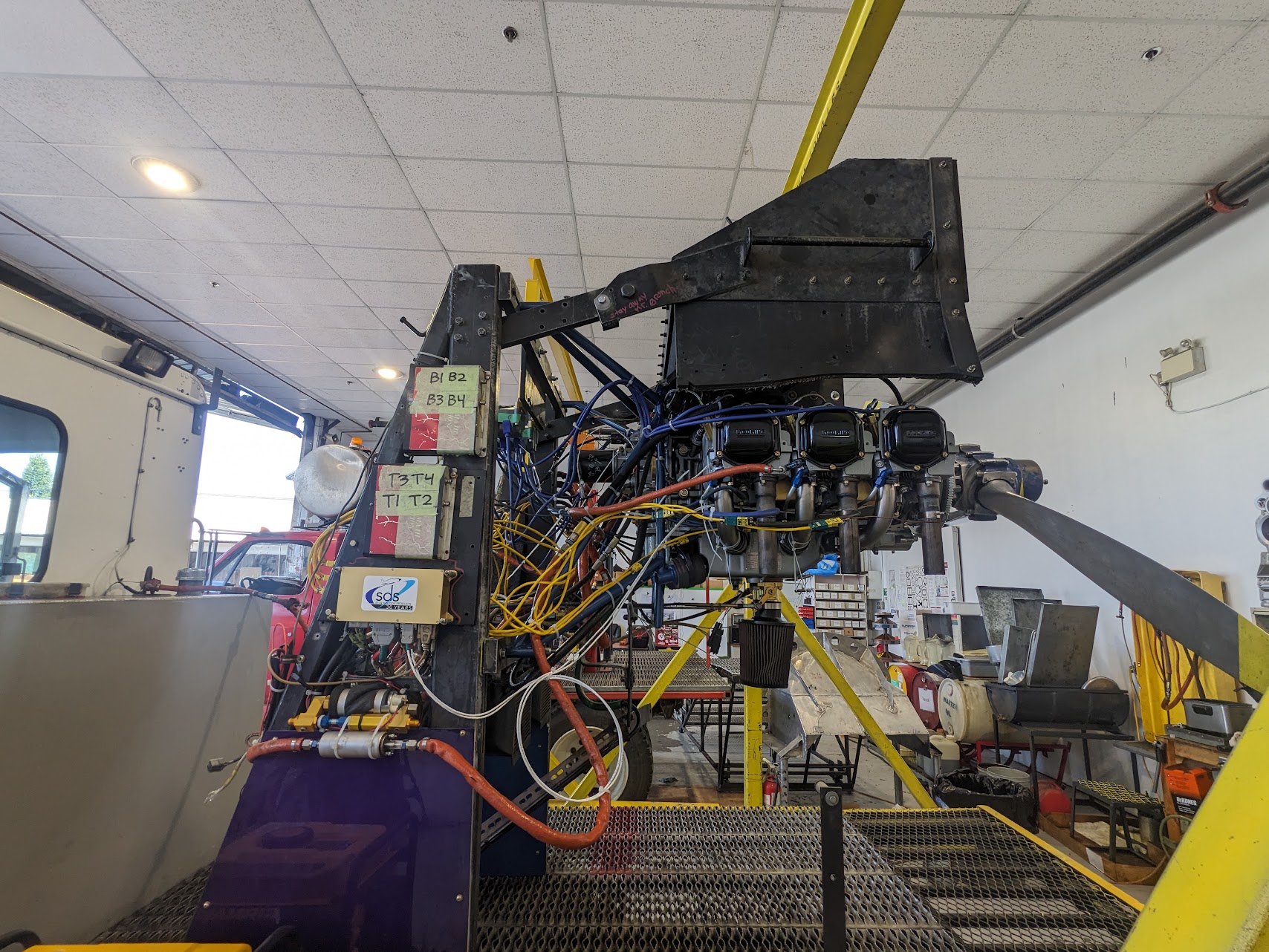
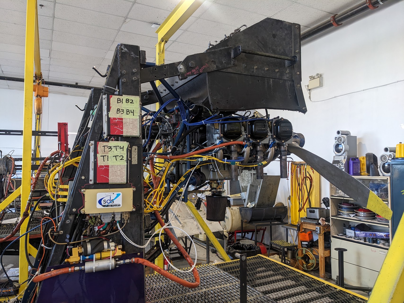
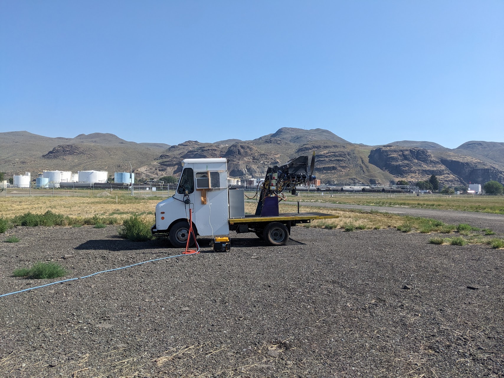
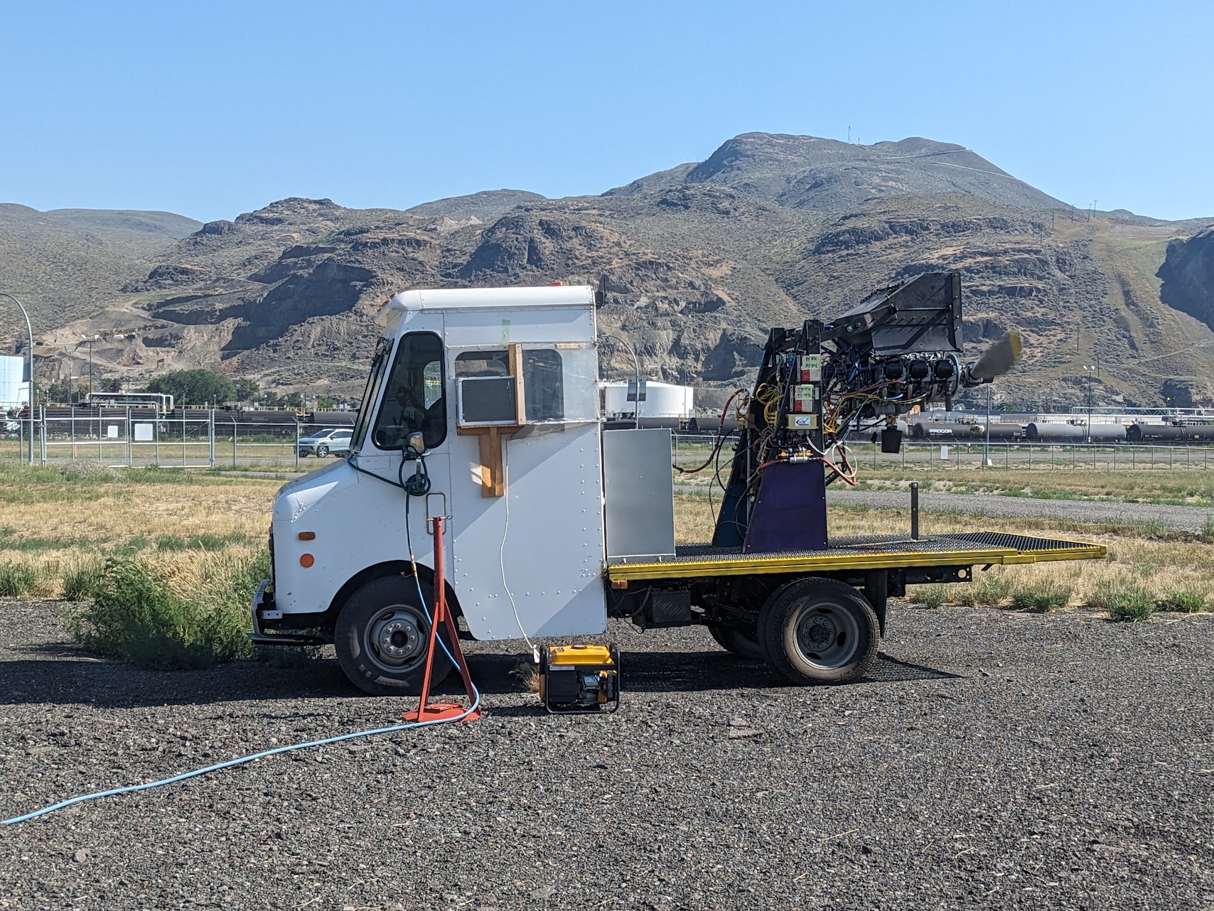
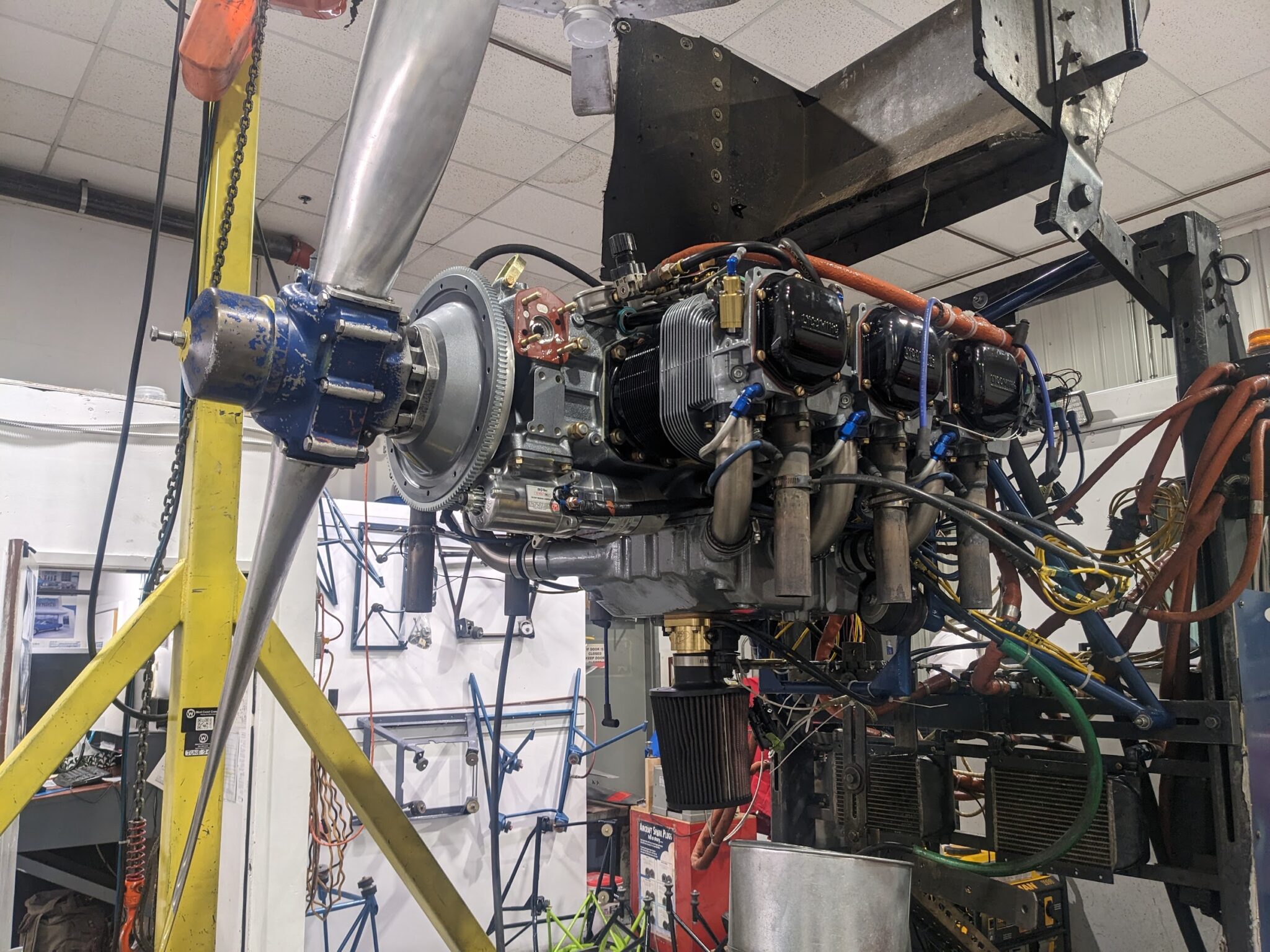
The engine is then mounted to a test truck. My SDS components were pre-mounted on the truck as this allows my ignition/injection system to be tested.
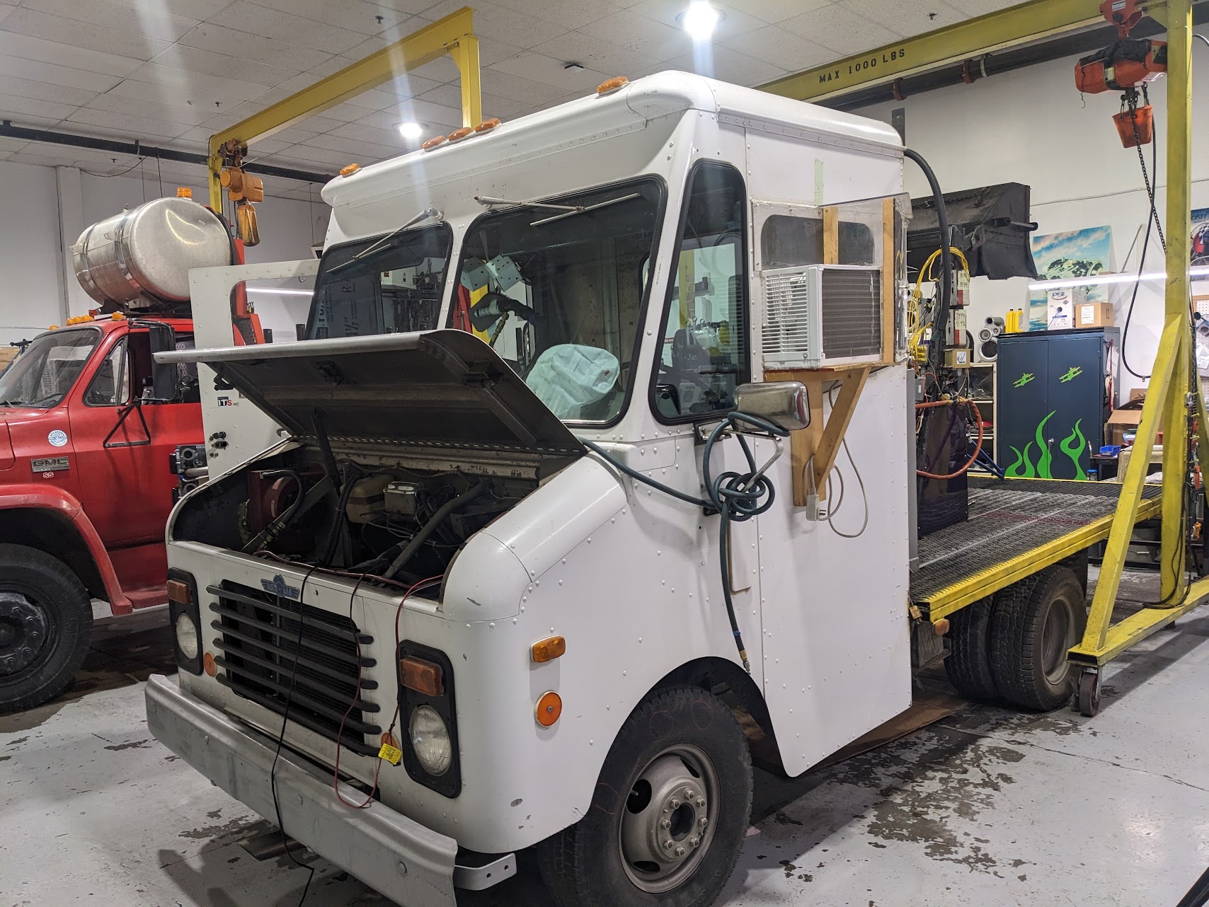
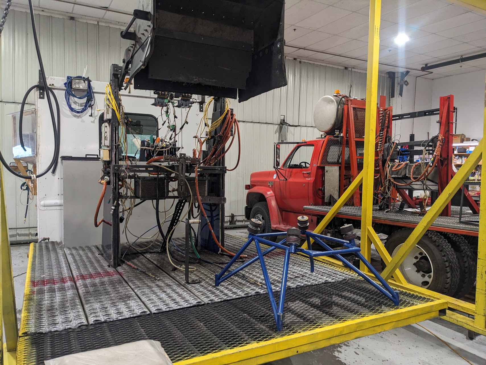
An engine mount was attached to the engine and the engine was mounted to the truck.
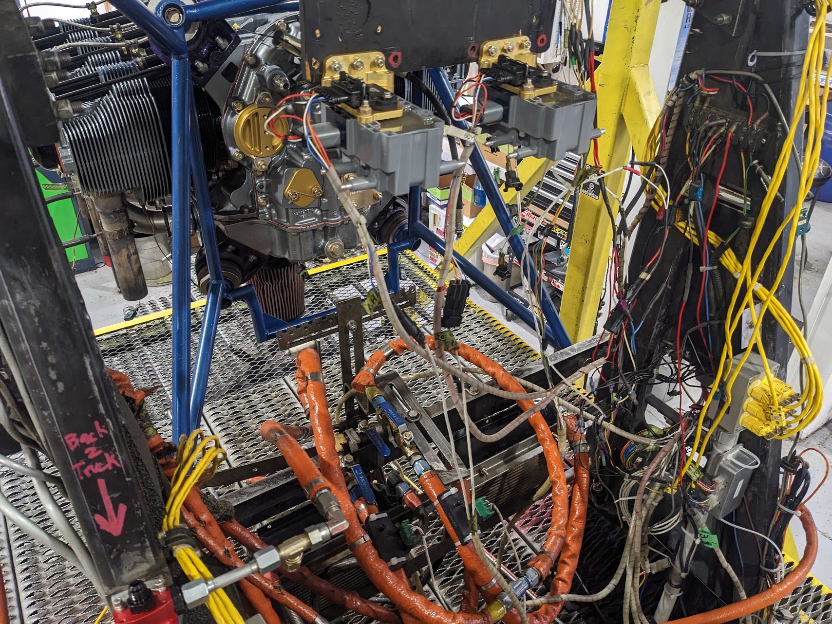
The coil packs from my SDS system mounted to the truck.
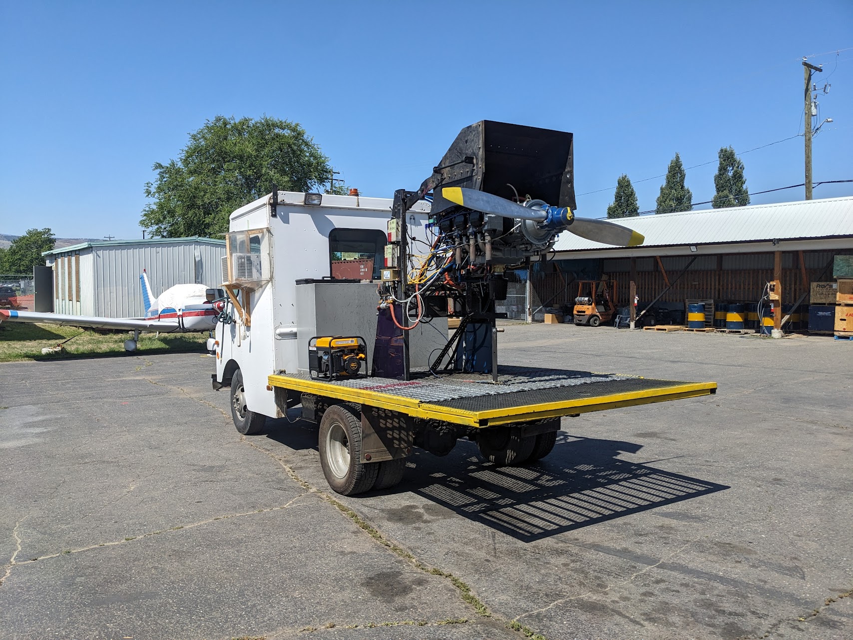
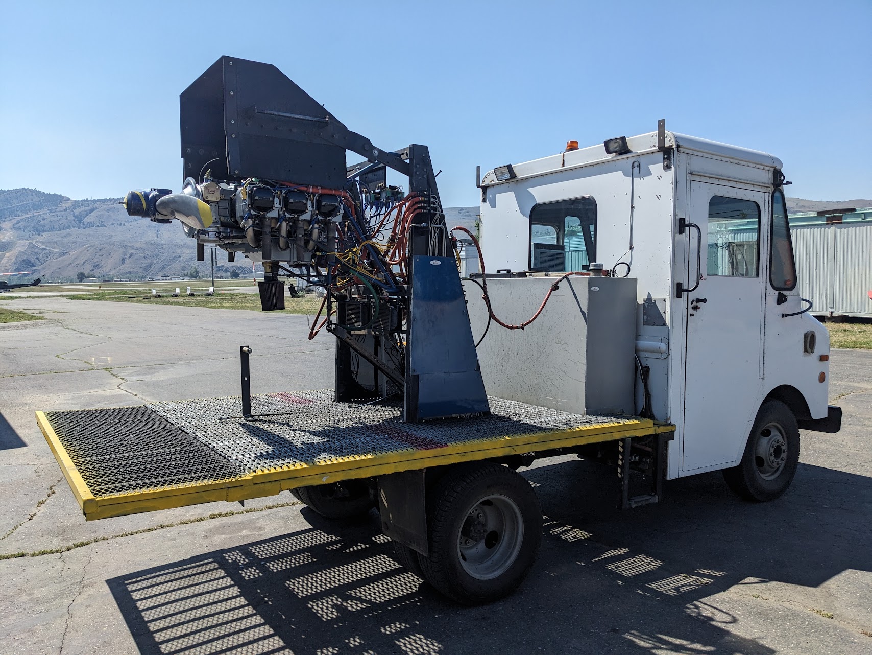
Day 3
Daytime temperatures were high so we did the test run in the morning. The engine is hot-potted with oil ahead of the test run to make sure everything is well-lubricated for the first start.
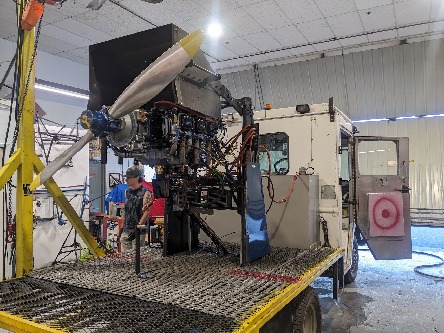
The cooling shroud directs air down through the engine.
The engine fired up on the first attempt. The puff of smoke is the burning off of the grease that was added during the build.
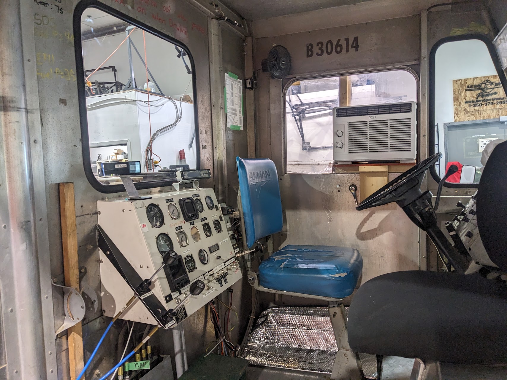
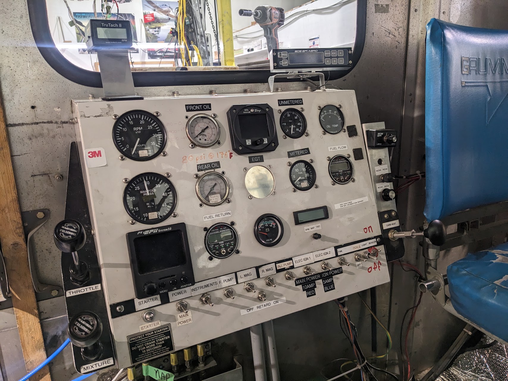
Engine oil pressure is adjusted manually based on the readings from the test rig.
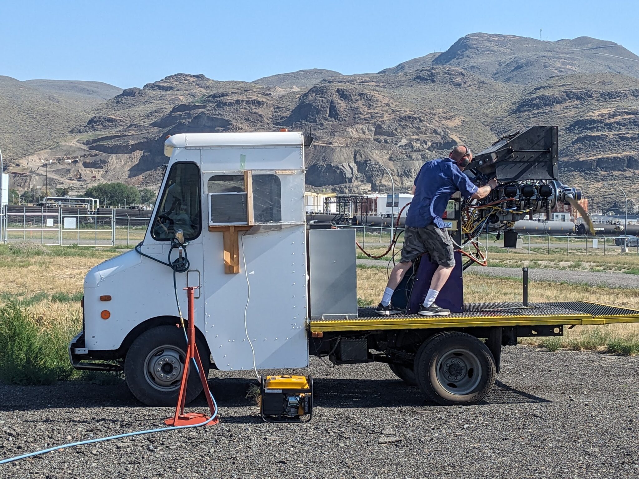
The engine then goes through a range of RPMs for a test sequence that lasts about an hour.
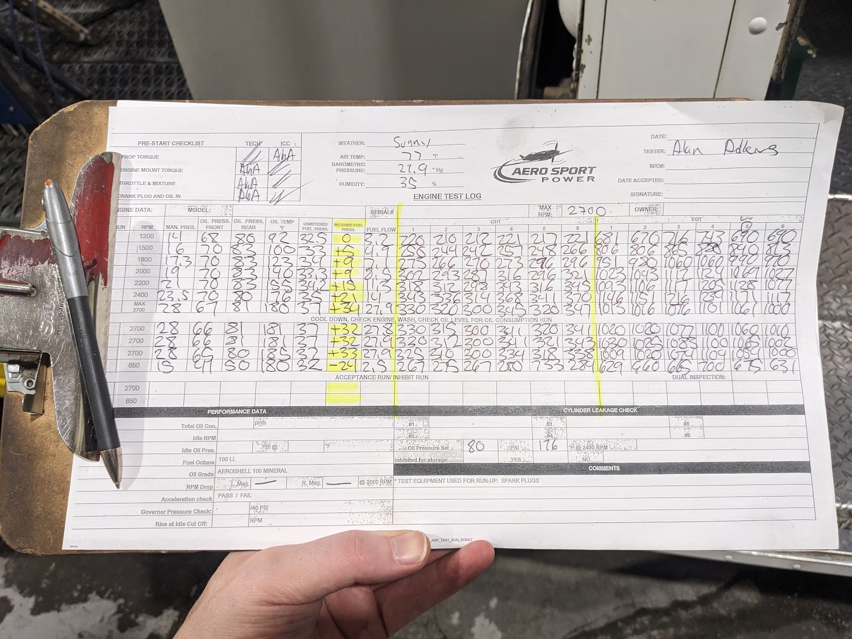
The engine is inspected, compression tested, and then sent out for an additional run where the numbers are verified by a second tech. The oil is changed to an oil to preserve the engine.
The engine will be crated and shipped to me. The build school was an awesome experience and I highly recommend it if you want to learn more about the internals of your engine. The team at Aero Sport Power was exceptional to work with from start to finish and I’m excited to get this mounted on the airplane.
The engine preservation is good for about a year so this has lit the fire to get the project completed! I’m hoping to be in the air by the spring/summer of 2025.