
The Garmin avionics that I am using provide support for a TO/GA (takeoff/go around) button. When used during a missed approach, this instructs the flight director to perform a straight-out wings-level climb and sequences the missed approach procedure on the navigator.
I preferred to add this as a thumb-activated button to my Aerosport center console throttle quadrant, allowing the button to be engaged while applying the throttle.
The GTN 650 and the GMC 507 provide discrete inputs to activate the mode on each device. To avoid needing a DPST button, diodes can be used to isolate the inputs allowing a single wire for both. The challenge then was to find a way to route this wire into the handle of the throttle lever.
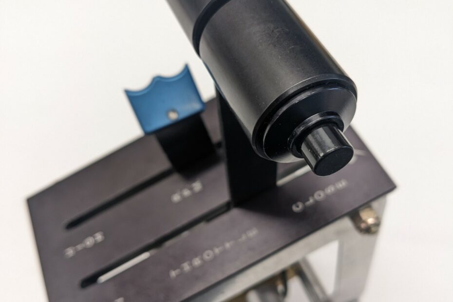
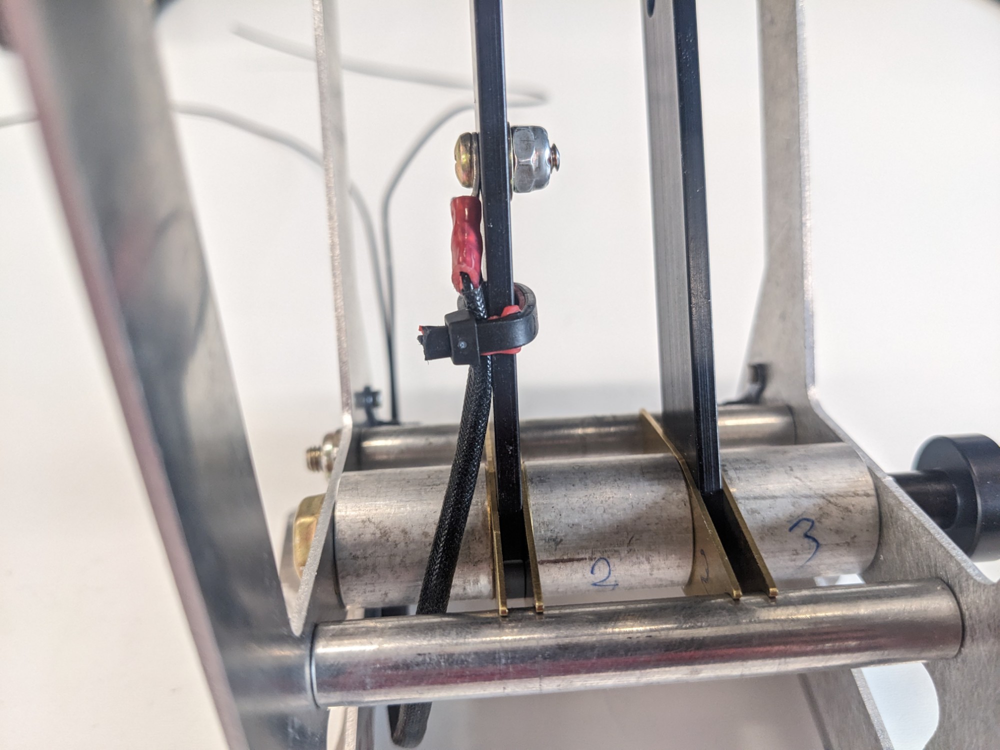
With some practice on some scrap, I determined that I could create a slot on the front of the throttle lever with a Dremel into which a 22 gauge wire could be pressed (note that I extended the slot further than shown in the picture below so that the wire exits below the throttle cable attach point). The slot hides the wire and ensures that the wire does not contact the stop in the full forward position. The black wire ends up being almost invisible against the black anodized finish of the lever. The ground path uses the aluminum lever.
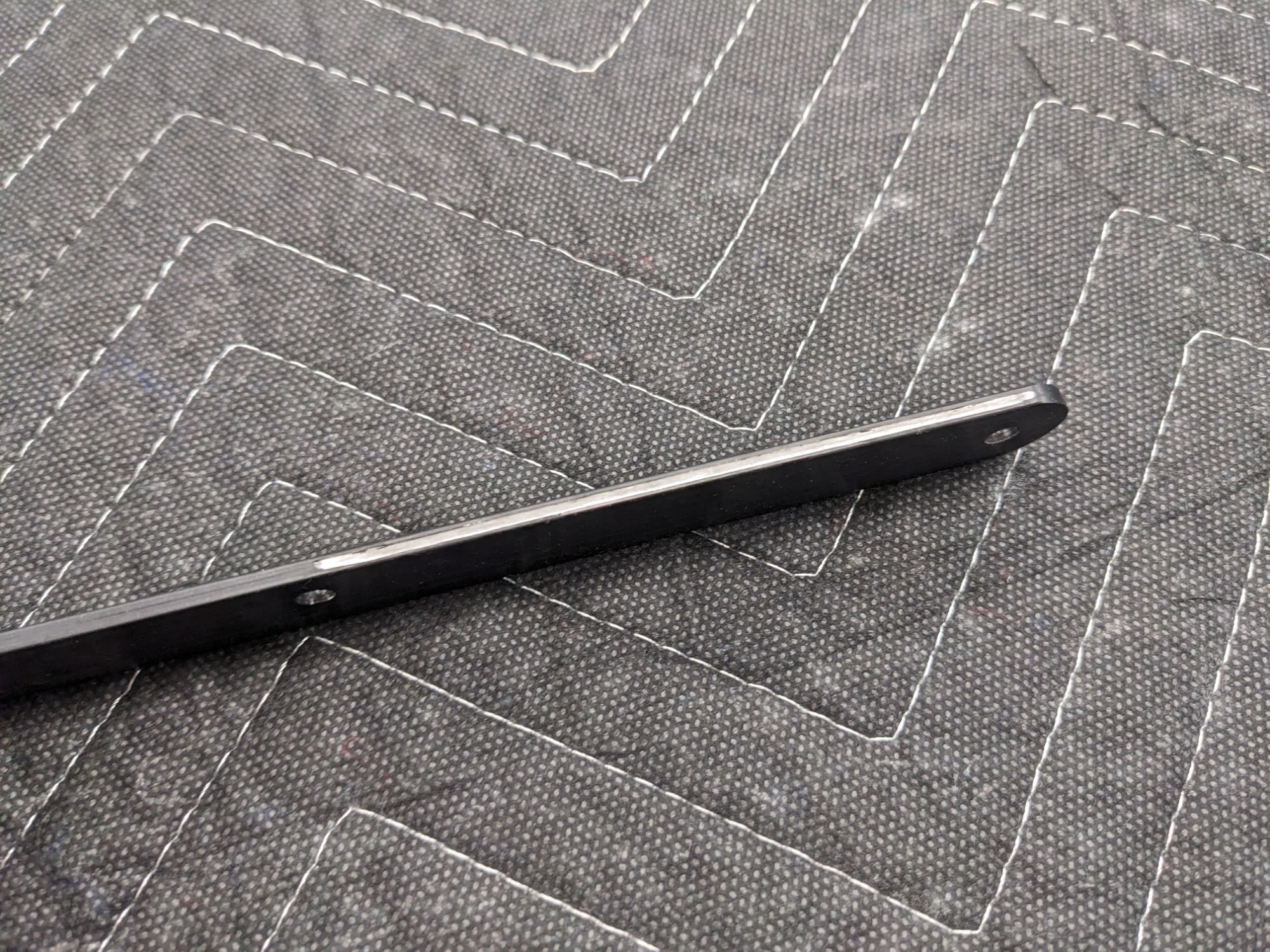
I drilled a 1/16″ hole in the base of the left throttle handle that intersected with the top of the slot. This allows the wire to be routed up the front of the lever and into the handle.
I drilled a second small hole through the left handle and lever that allows an anti-rotation pin to be inserted. This ensures that the bolted handle cannot rotate and impinge on the wire. This pin also extends into the left handle which I use to prevent the rotation of the insert that holds the button.
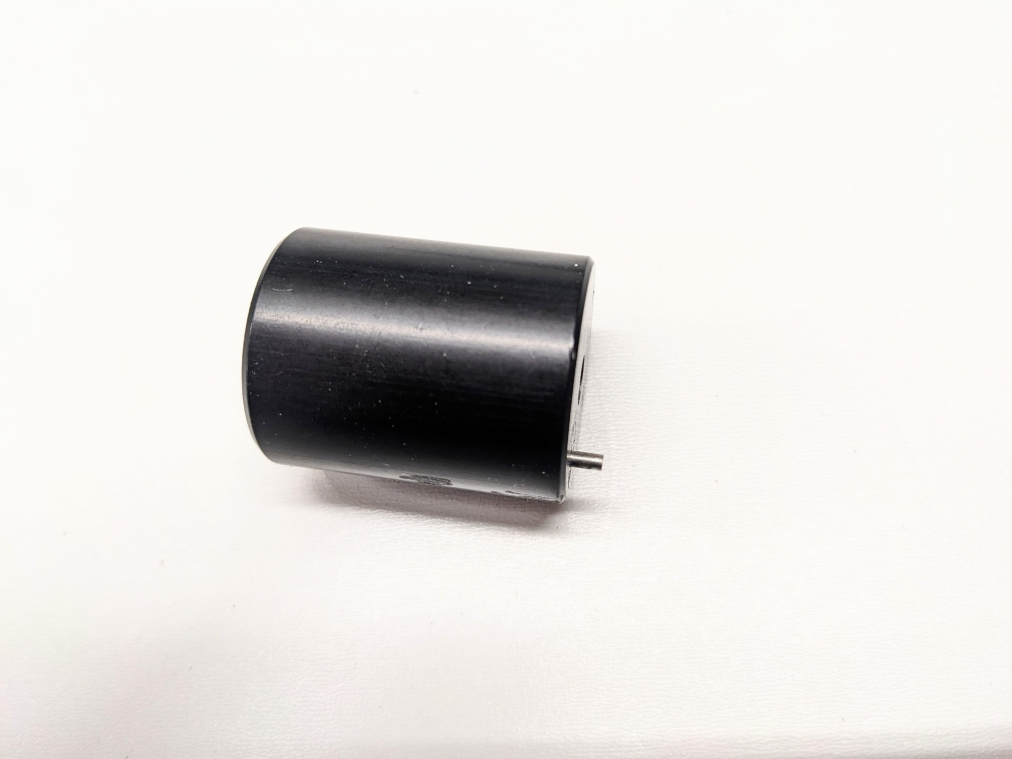
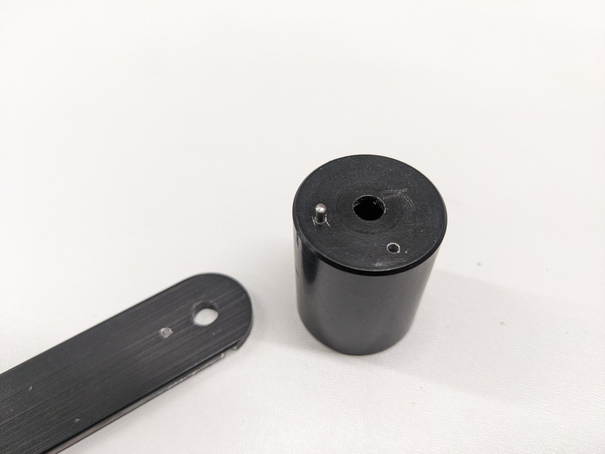
I selected a snap-action momentary push button that requires a 4 lb force to activate to prevent accidental presses.
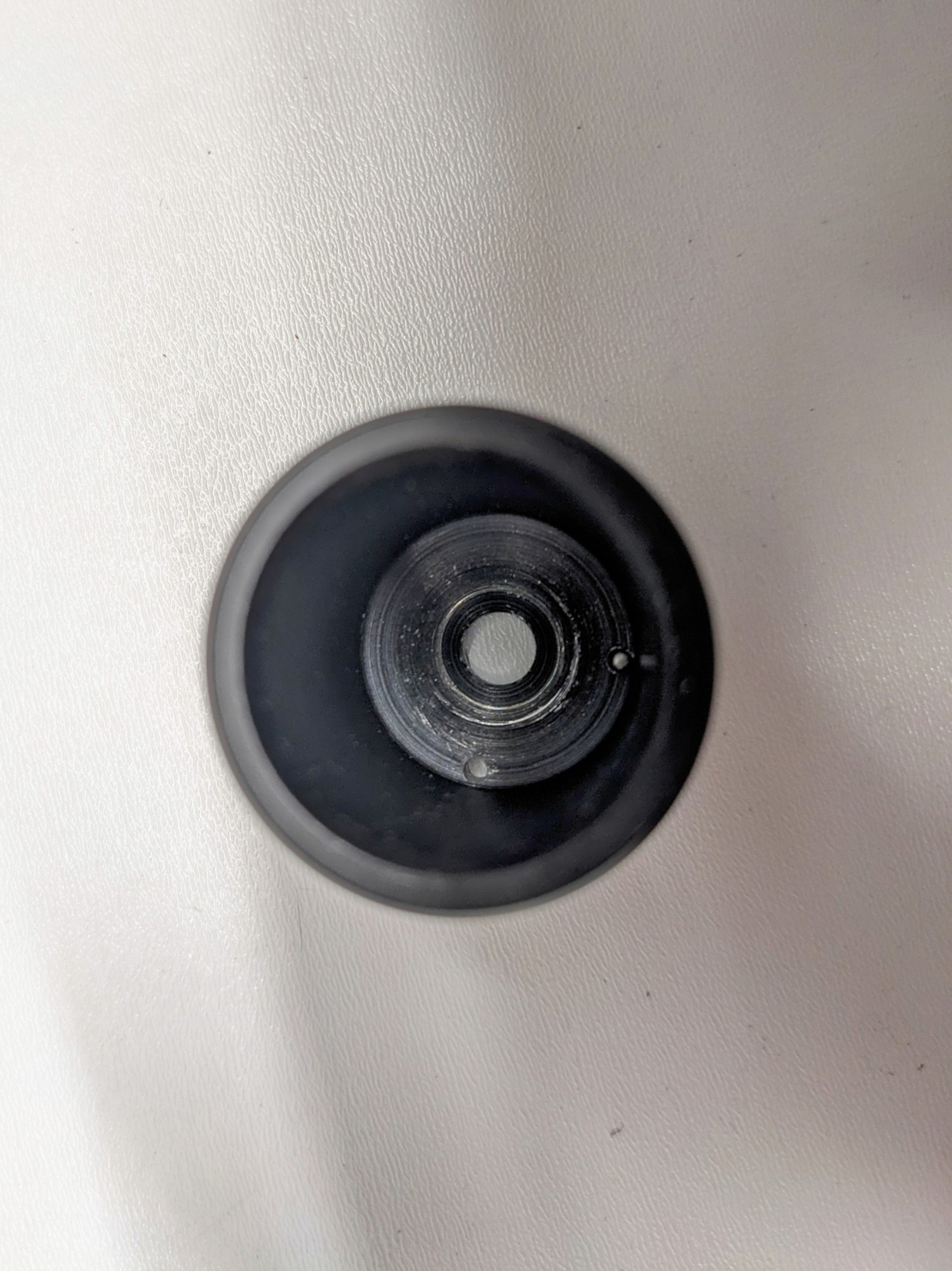
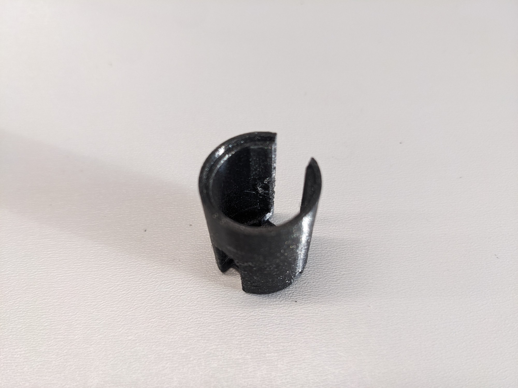
I designed a 3d printed insert that allows the button to be secured into the handle with the bolt. There isn’t sufficient room to use the threads so the button is held in place with compression instead.

I bent the button wire contacts to clear the head of the bolt. A ring terminal secures the ground to the throttle handle bolt. I soldered this to the terminal in the reverse direction to provide a length of extra wire, necessary for assembly. The slot in the insert allows this wire to be looped back on itself.
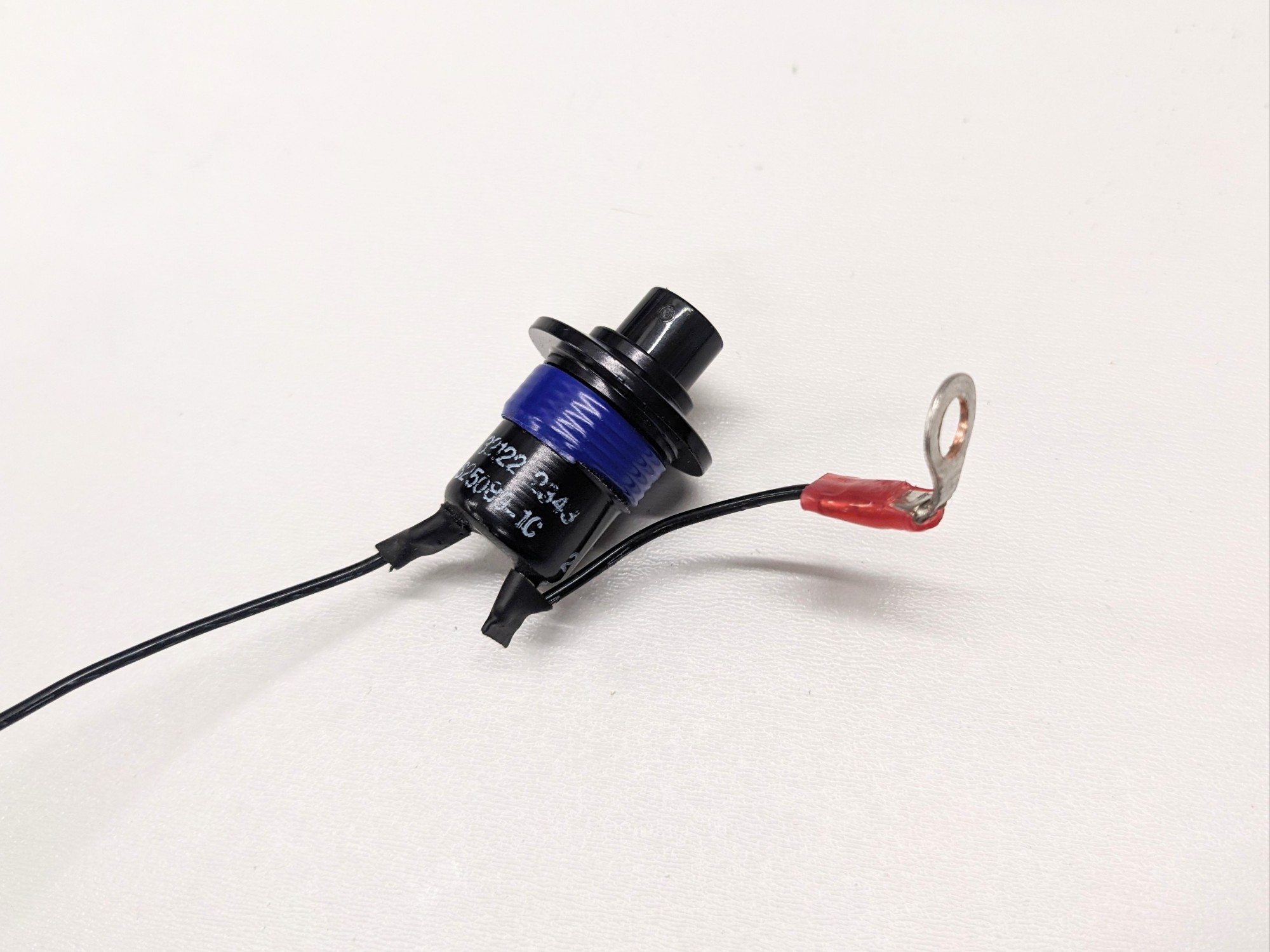
The bolt is inserted through a hole in the bottom of the insert which secures the insert into the throttle handle. The ring terminal goes over the bolt and a washer is used to create a solid ground connection with the base of the throttle handle when the handle is reassembled and torqued.
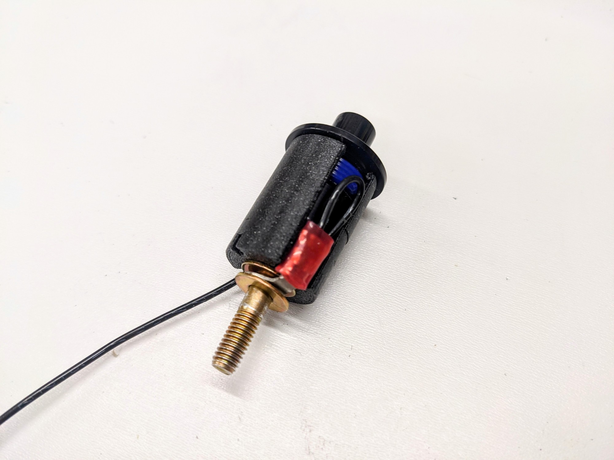
The input wire is then fed through the hole in the bottom of the handle and the assembly is pressed into place. The insert is tapered slightly to compress around the button.
The handle is assembled normally and the bolt holds the insert in place. The wire is then routed down the slot in the front of the lever and glued into place.
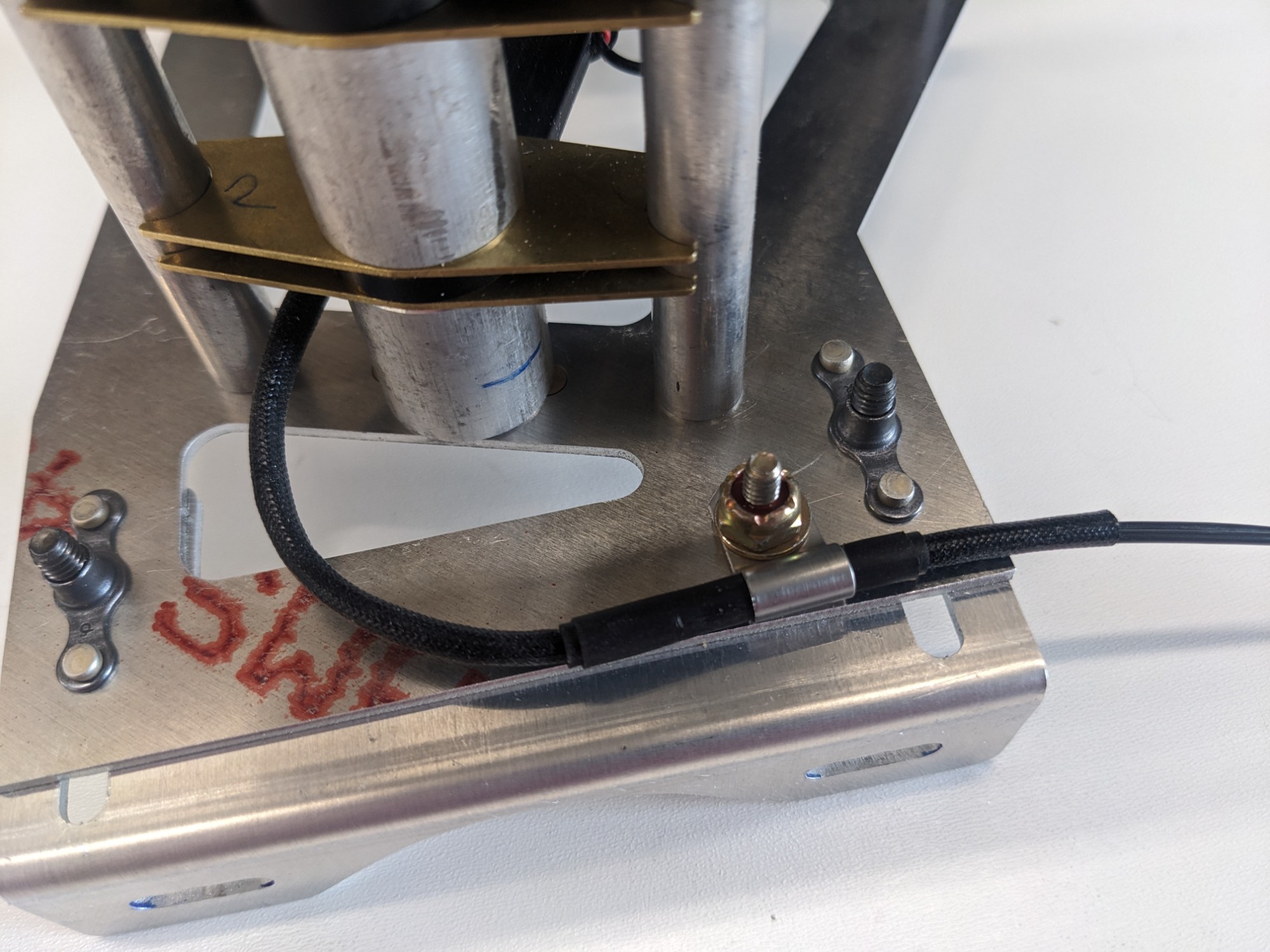
I attached a dedicated ground wire to the lever with a ring terminal that will connect back to the ground of the discrete inputs. The quadrant is already grounded through the airframe but I didn’t want to rely on that as a ground path.
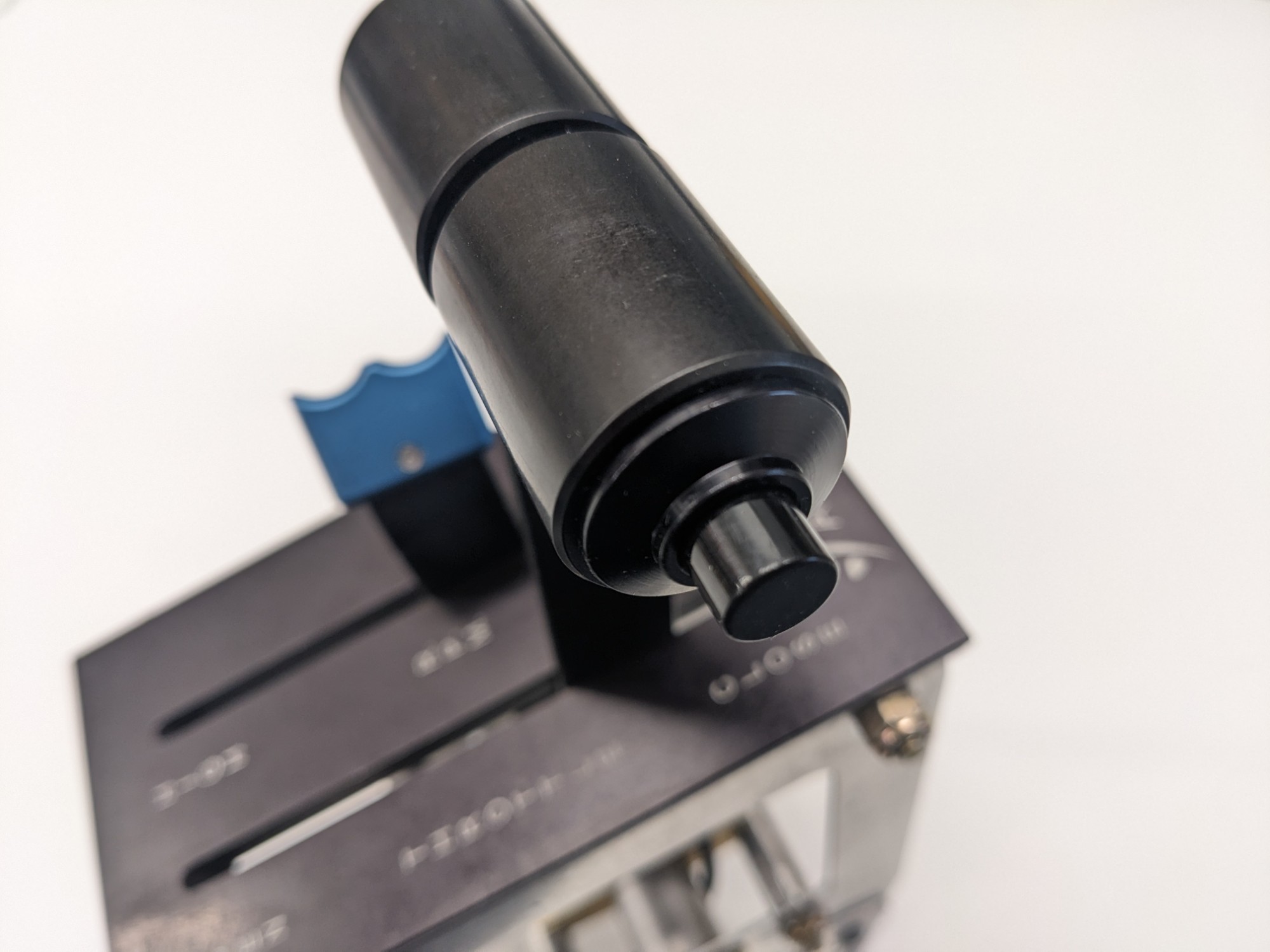
I’m very happy with how it came out after committing to taking a Dremel to the quadrant. The button looks like it was intended to be part of the quadrant
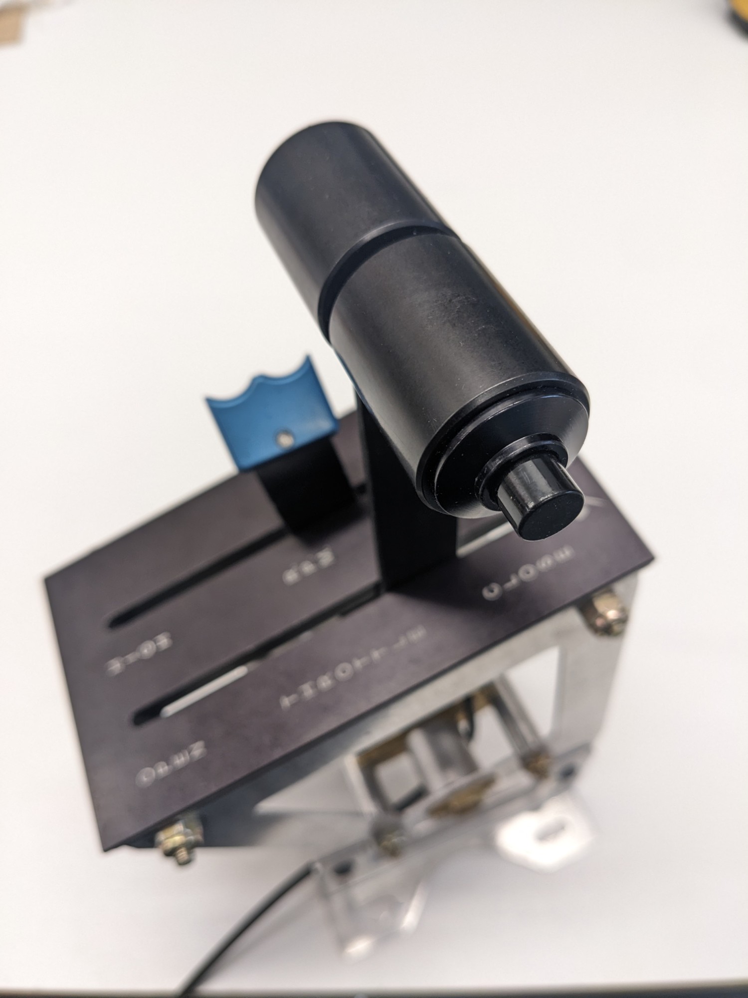
Success! I’m looking forward to seeing how this works in practice.