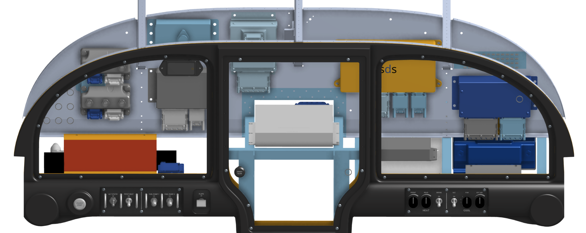
I have chosen to design and build my avionics wiring harness so I have been spending most of my build time lately working on wiring diagrams and a CAD model of my panel and sub panel.
Creating a comprehensive wiring diagram has been a significant amount of work and I’m finally getting close to documenting every connection in the electrical system.
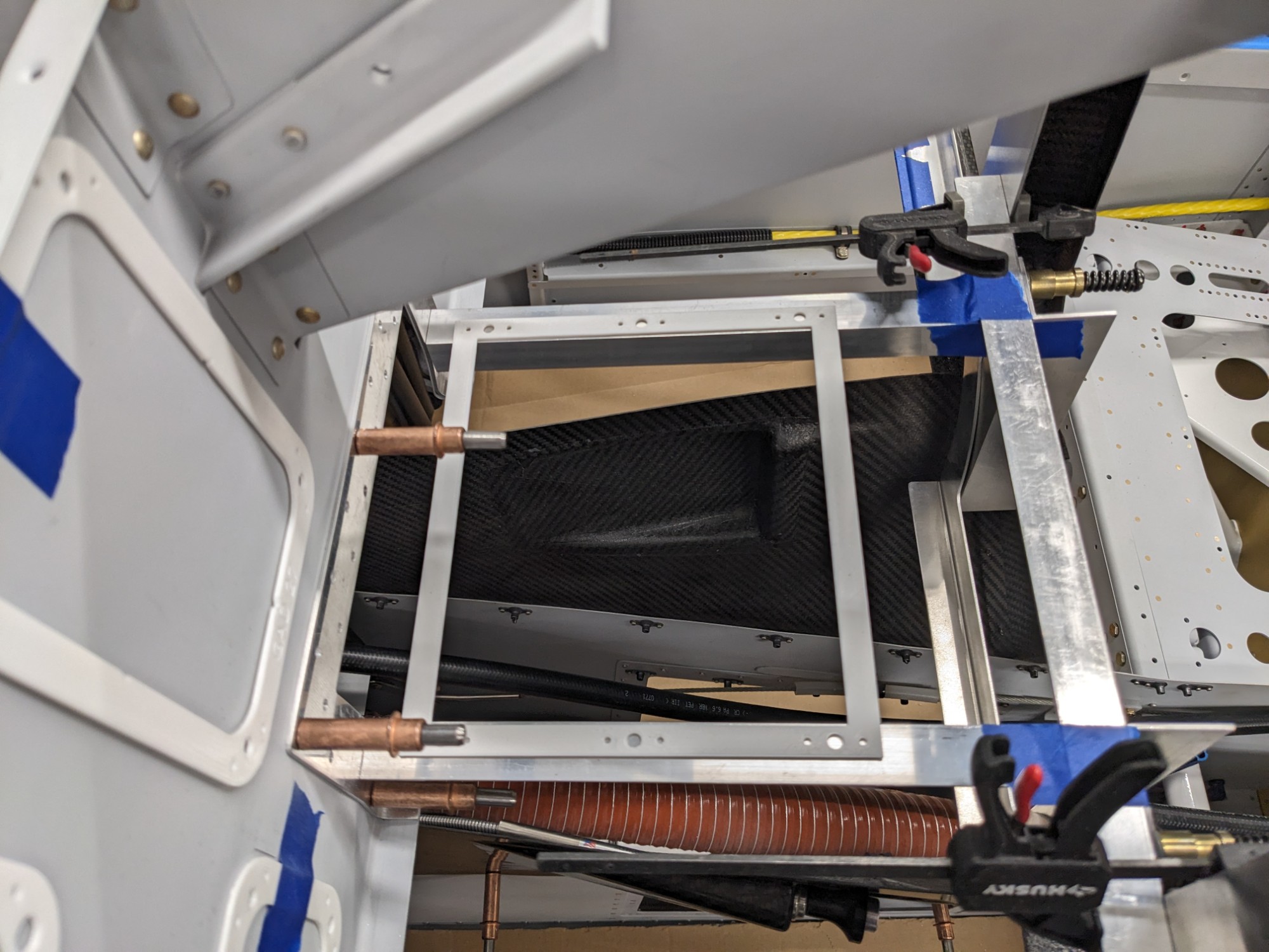
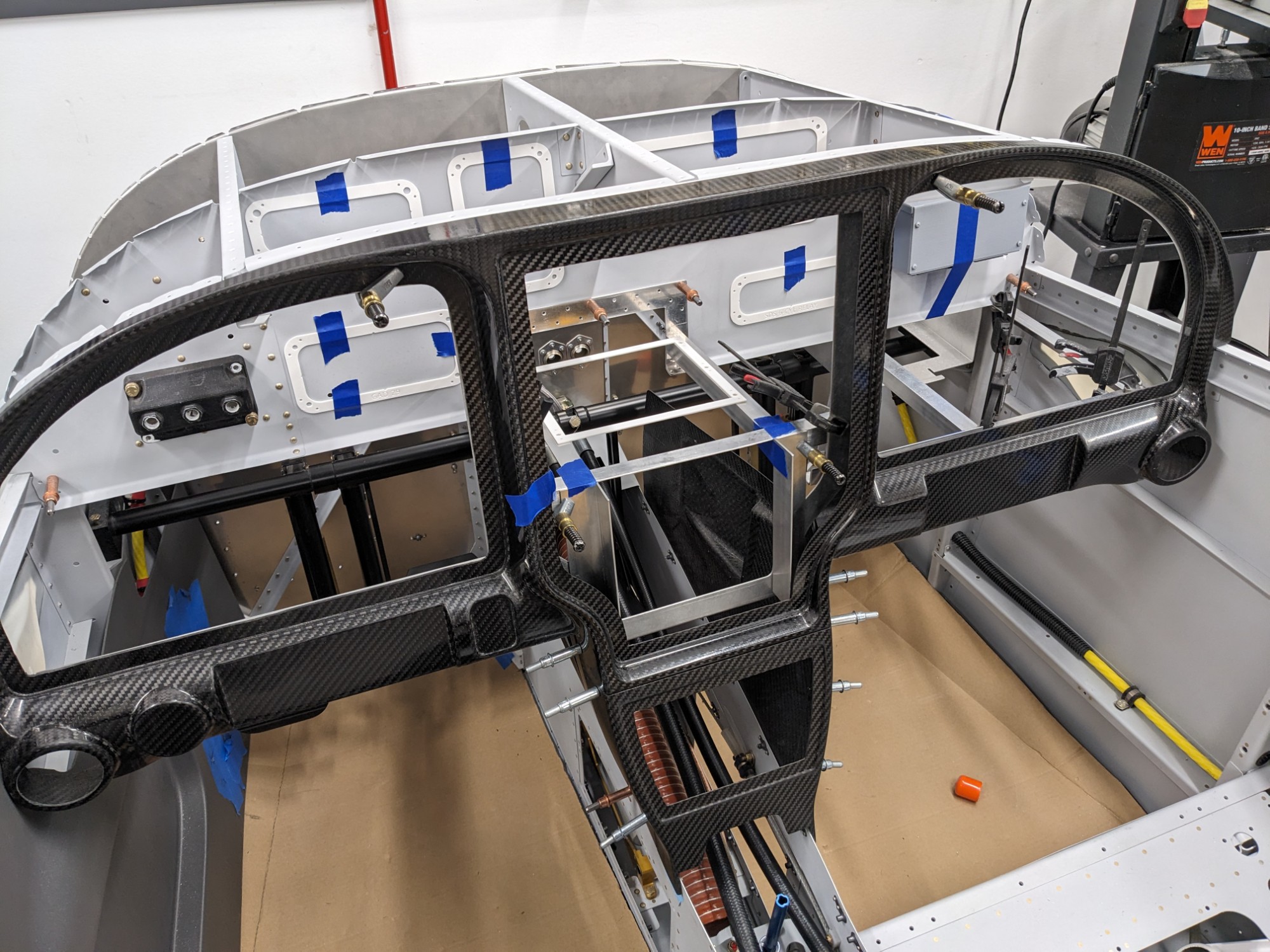
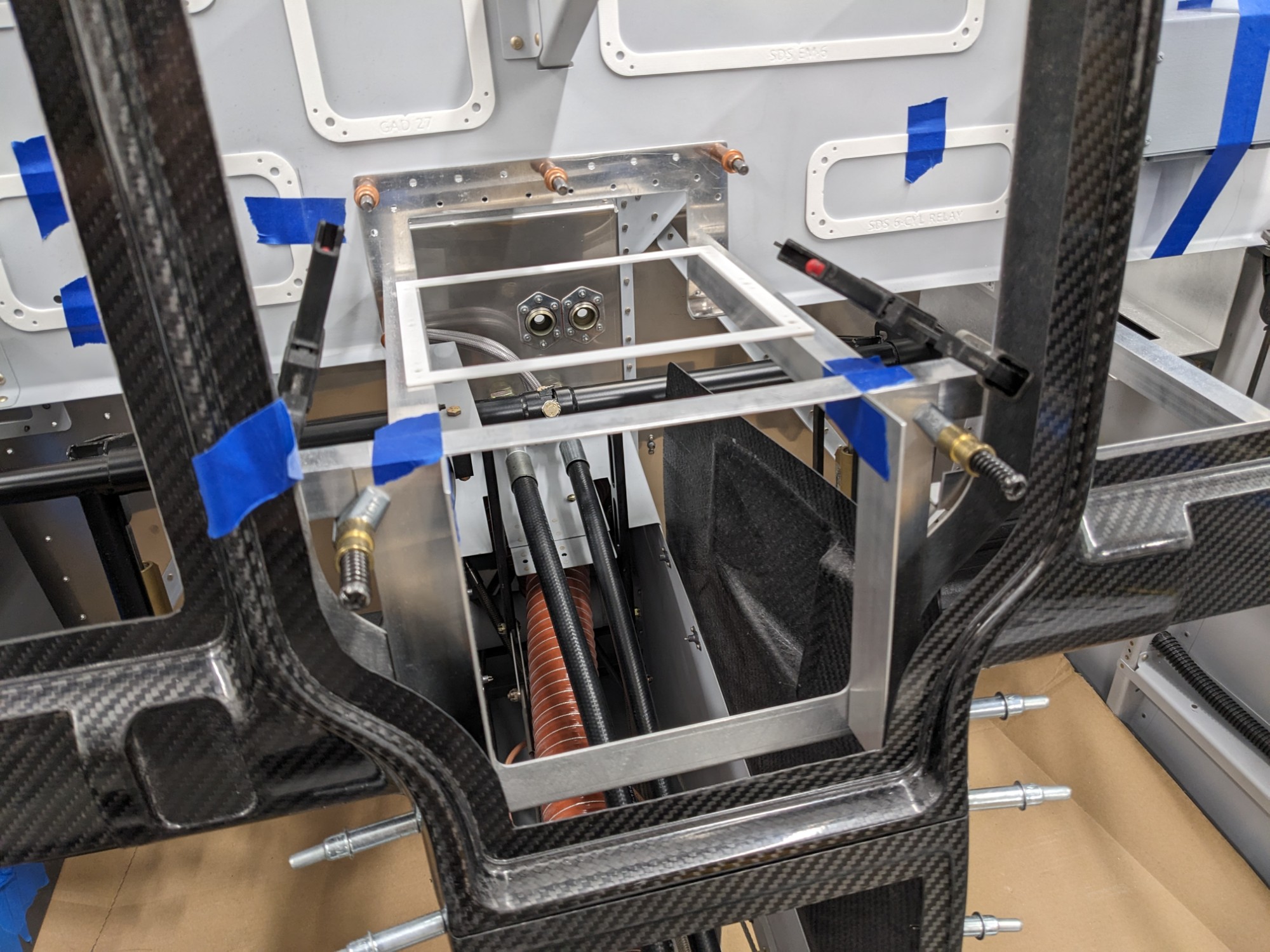
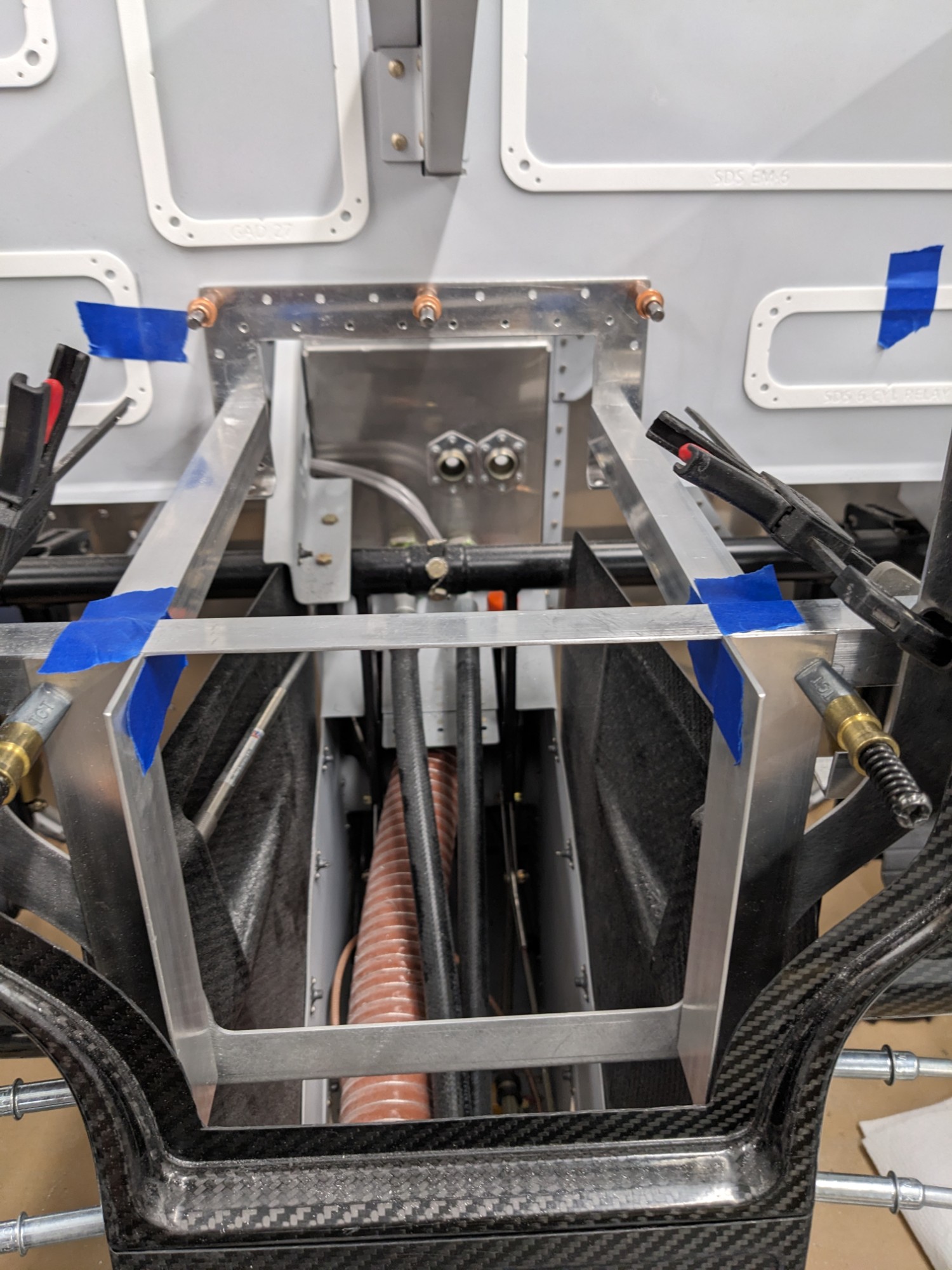
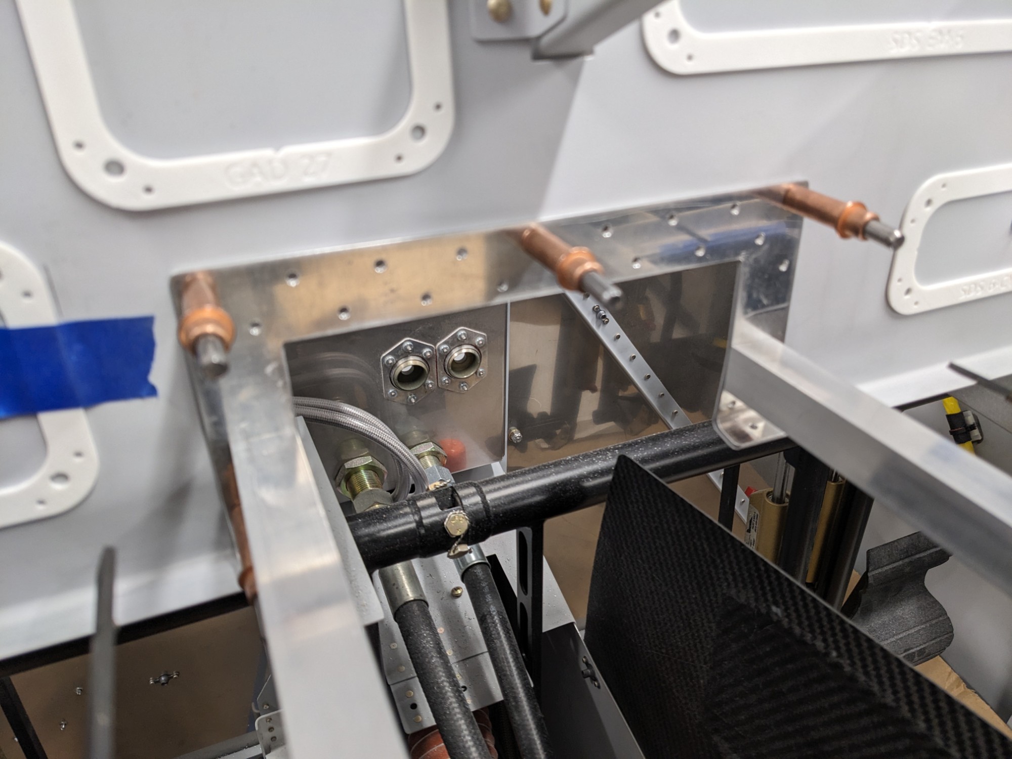
I have chosen to go with a dual-battery, dual-alternator architecture (the latter being a Monkworkz MZ-30L generator) with the second battery being installed under the subpanel. I will be using the Earth ETX900 vented battery in this location with a regular ETX900 behind the baggage compartment. The forward battery position allows me to run my electronic ignitions and injectors from an essential battery bus, allowing the engine to continue running with everything else off. The battery is mounted near the fuse panel that supplies power to the SDS EFI components.
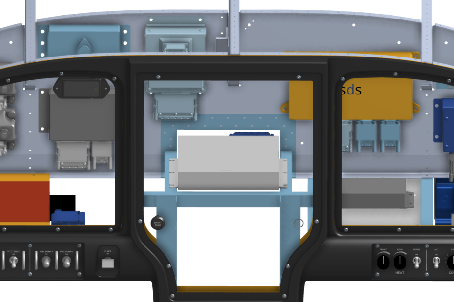
I have been using Garmin CAD models to lay out the panel digitally. I have also been using 3D printed versions to validate the selected locations to ensure appropriate clearances for connectors and mounting hardware.
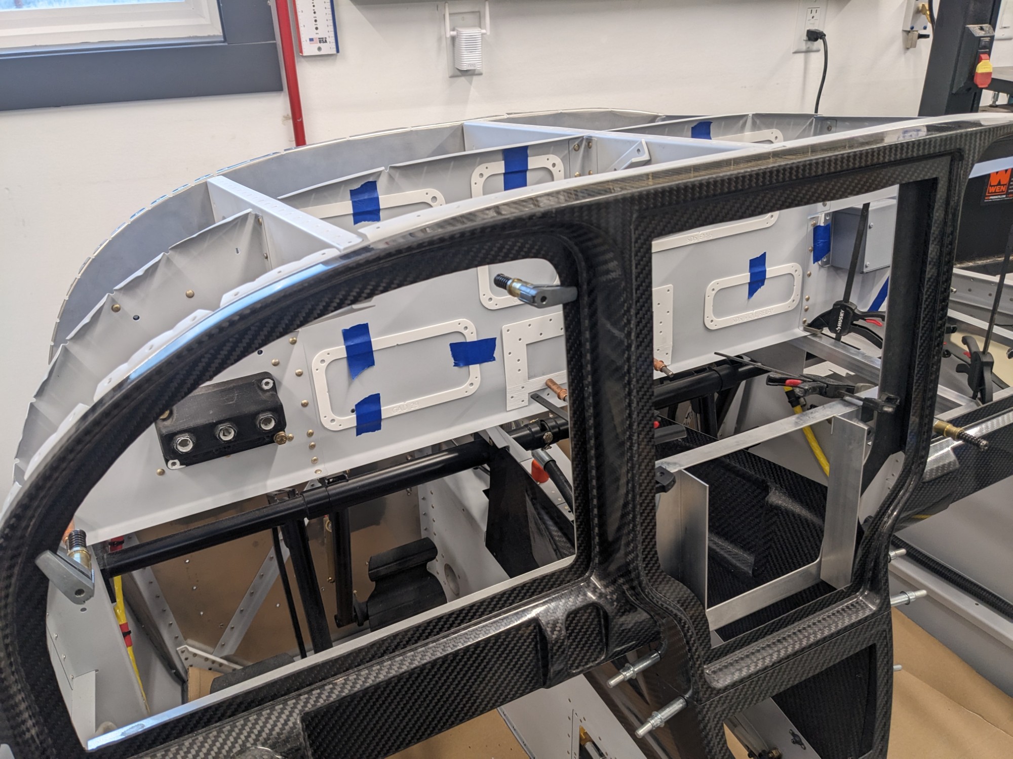
I will be installing a GTN 650 IFR navigator, a GMA 245 audio panel, and a GMC 507 autopilot controller below the center MFD. I prepared the parts for building a rack for installing these components. I’ll finish the rack after I get the panel insert cut.
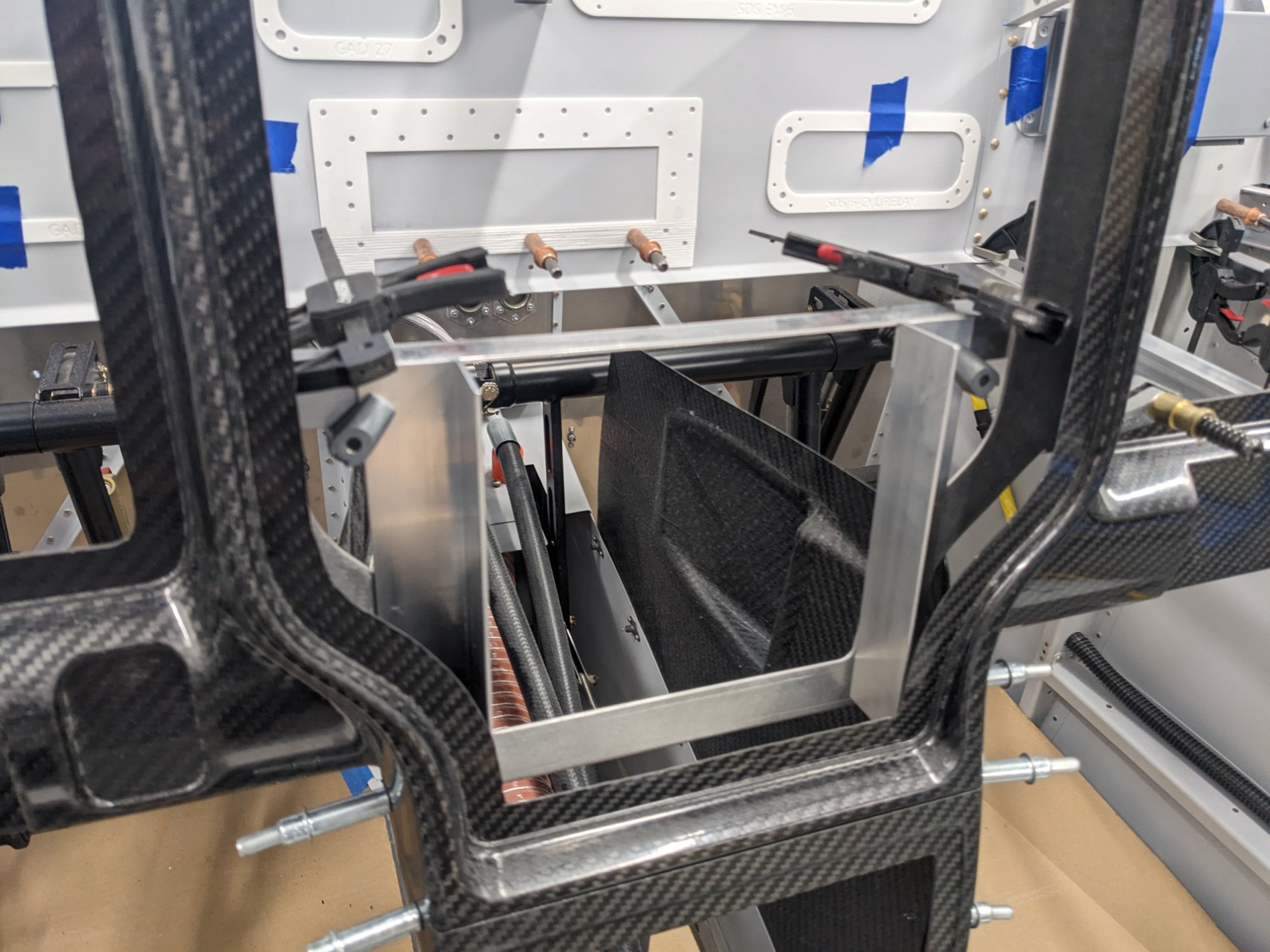
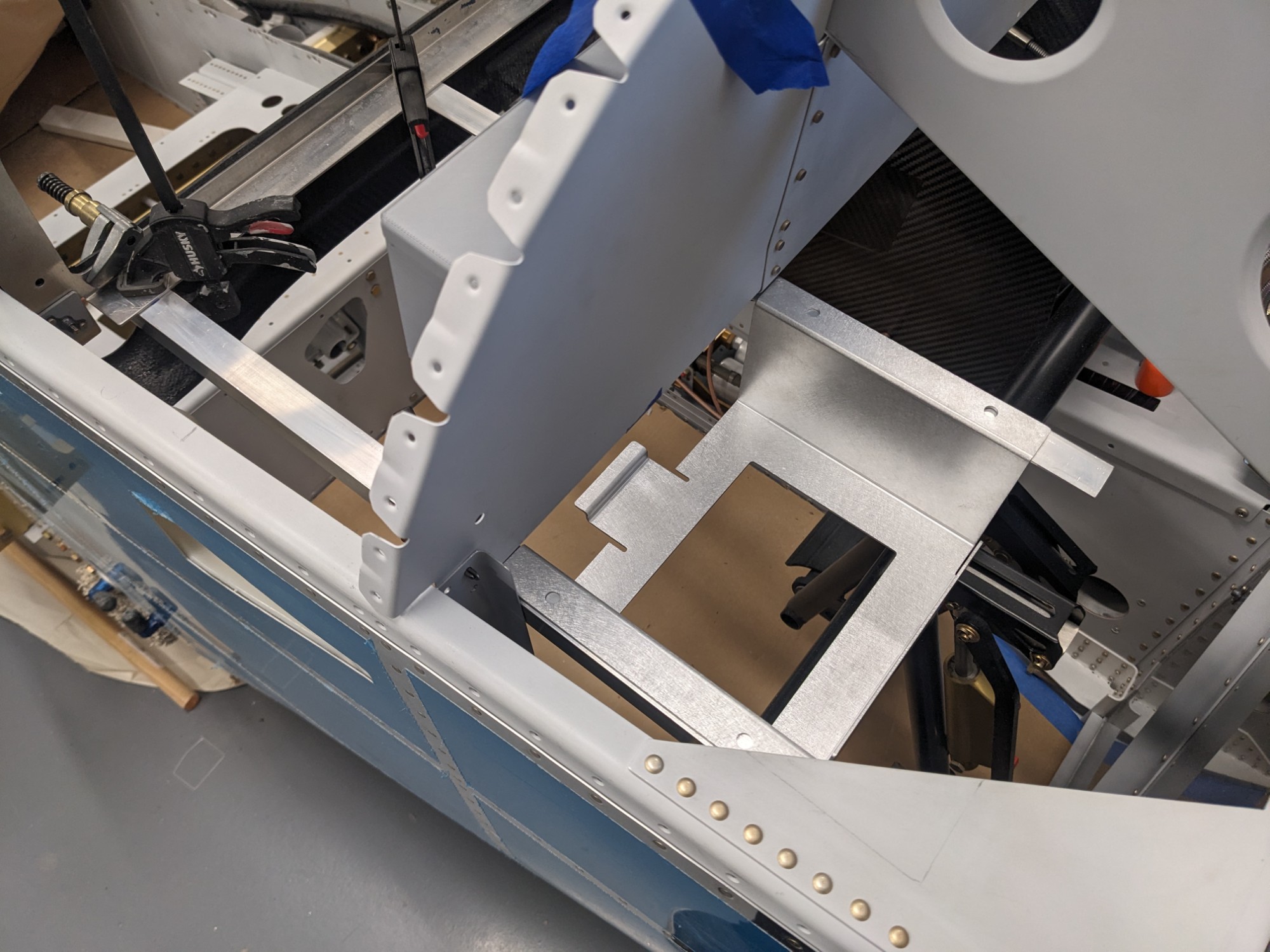
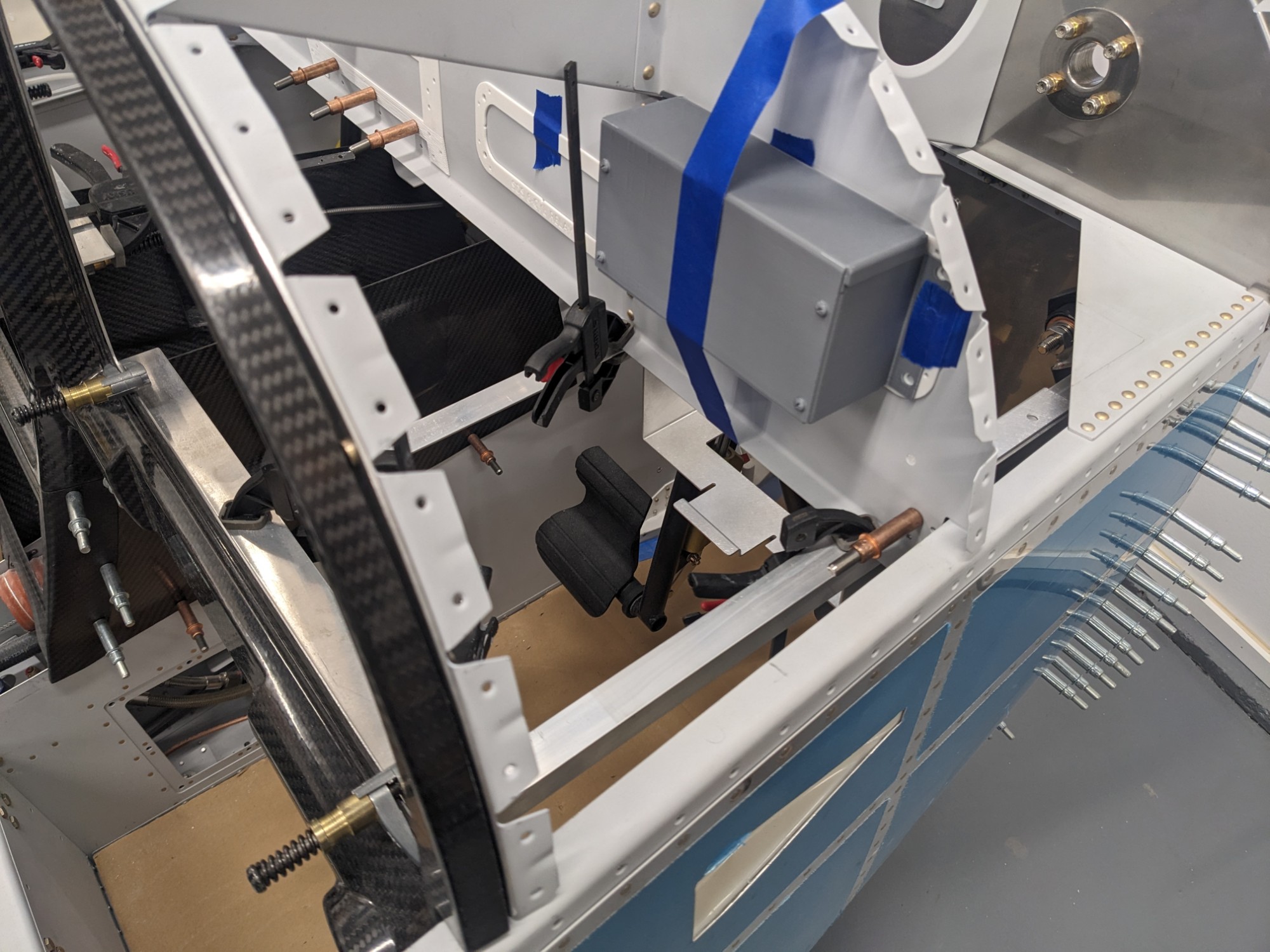
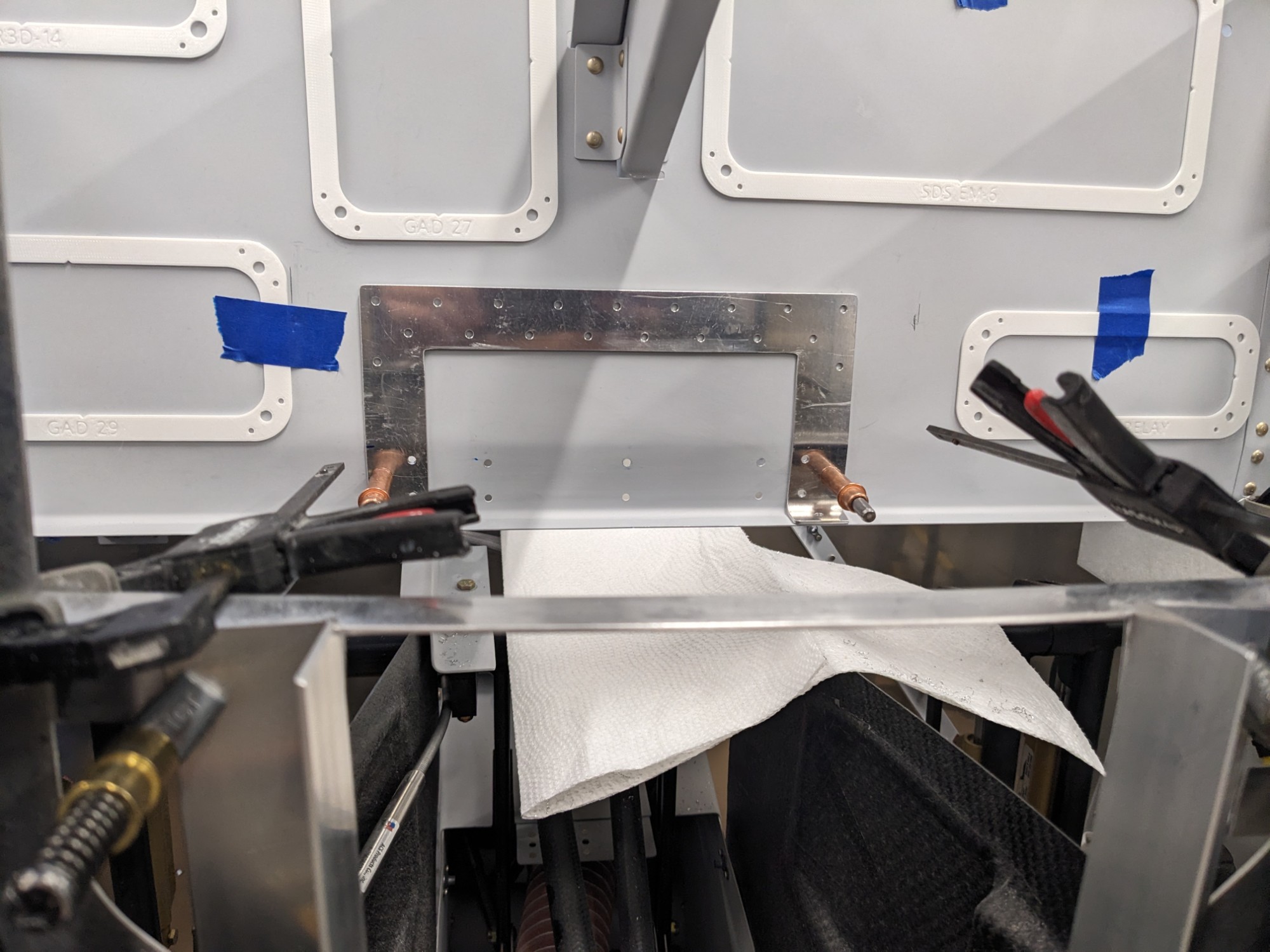
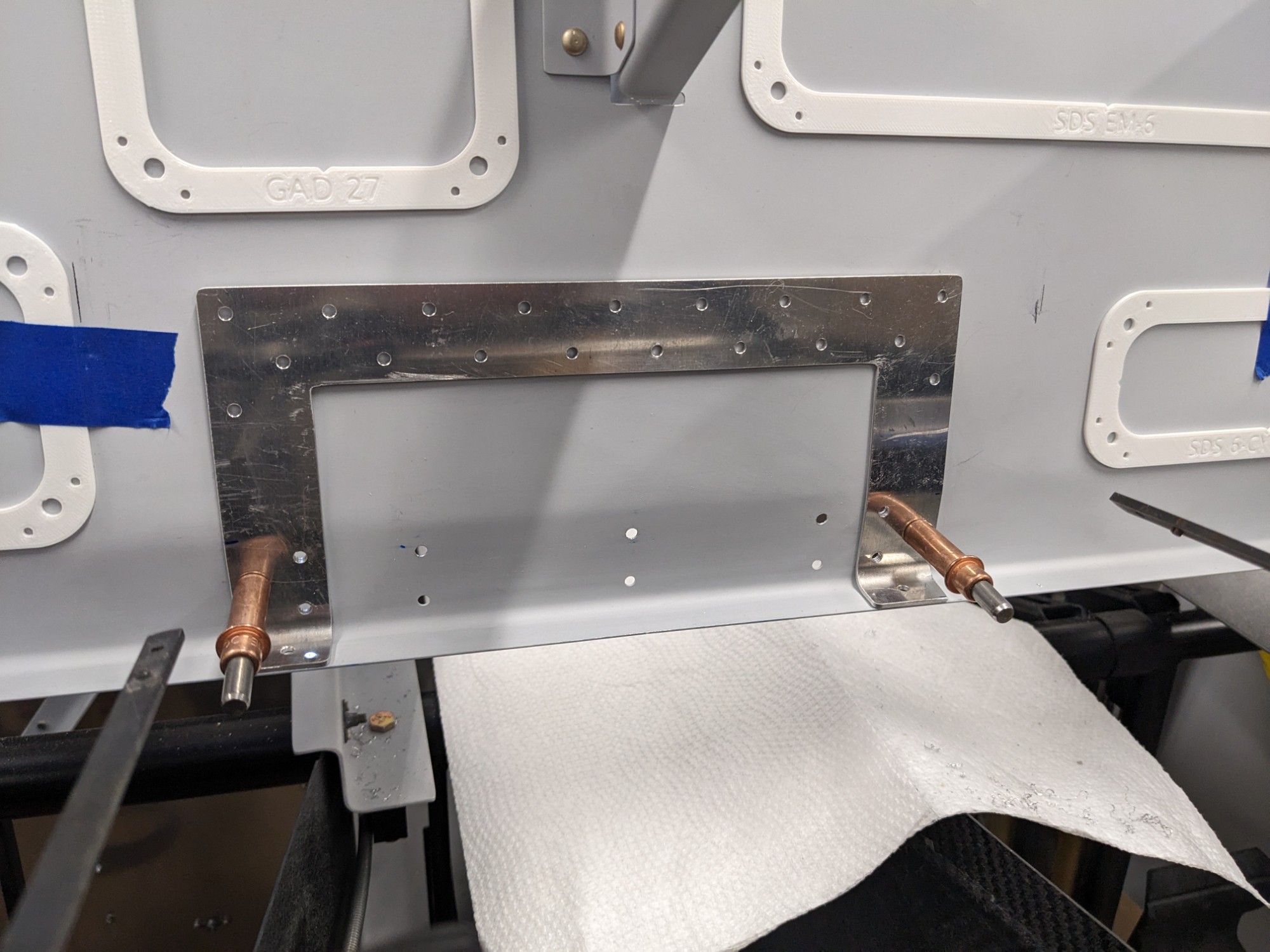
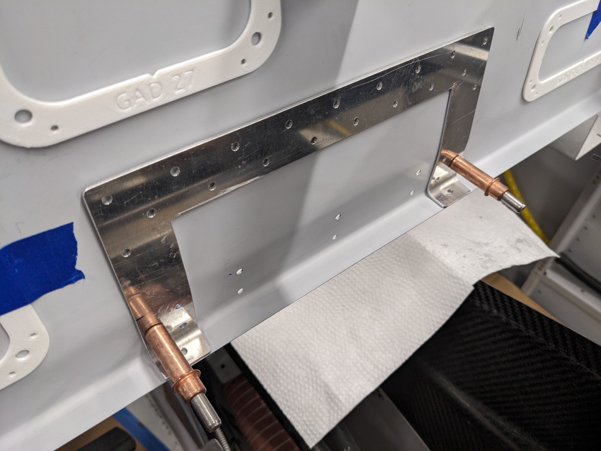
The GTN 650 is deeper than the subpanel, so I cut the subpanel and installed a doubler here per the specs in the plans. I used my panel CAD model to determine the position of the opening and used a 3D printed mockup from that model to help create the doubler.
My remote mount COM 2 radio (a GTR 20) will be mounted on top of the radio stack behind the center MFD.