
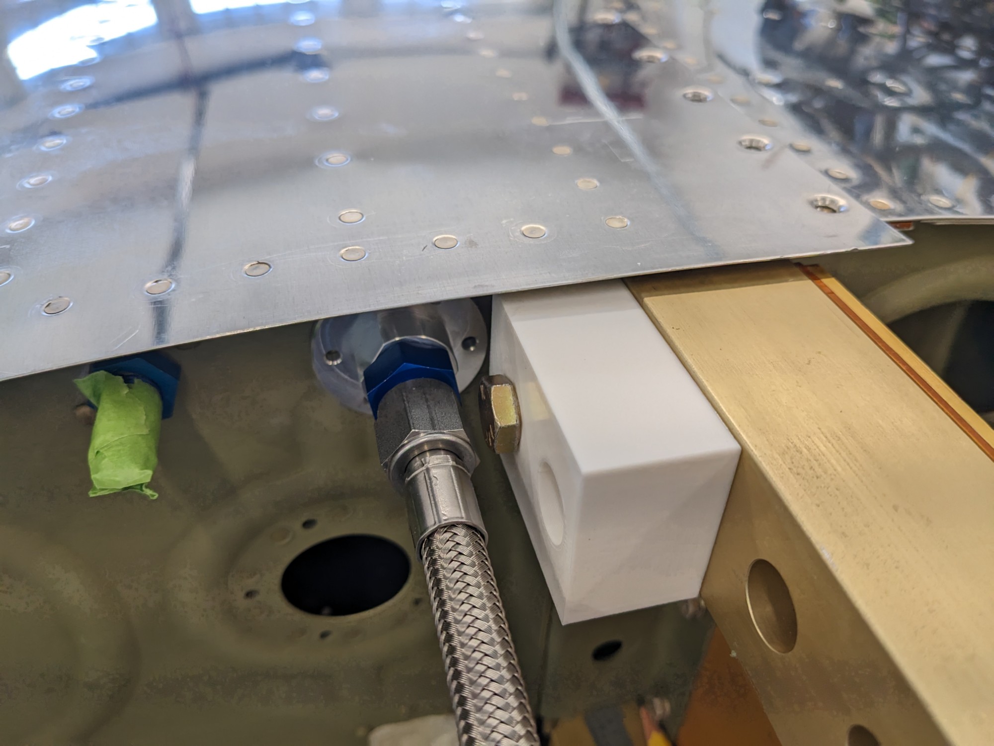
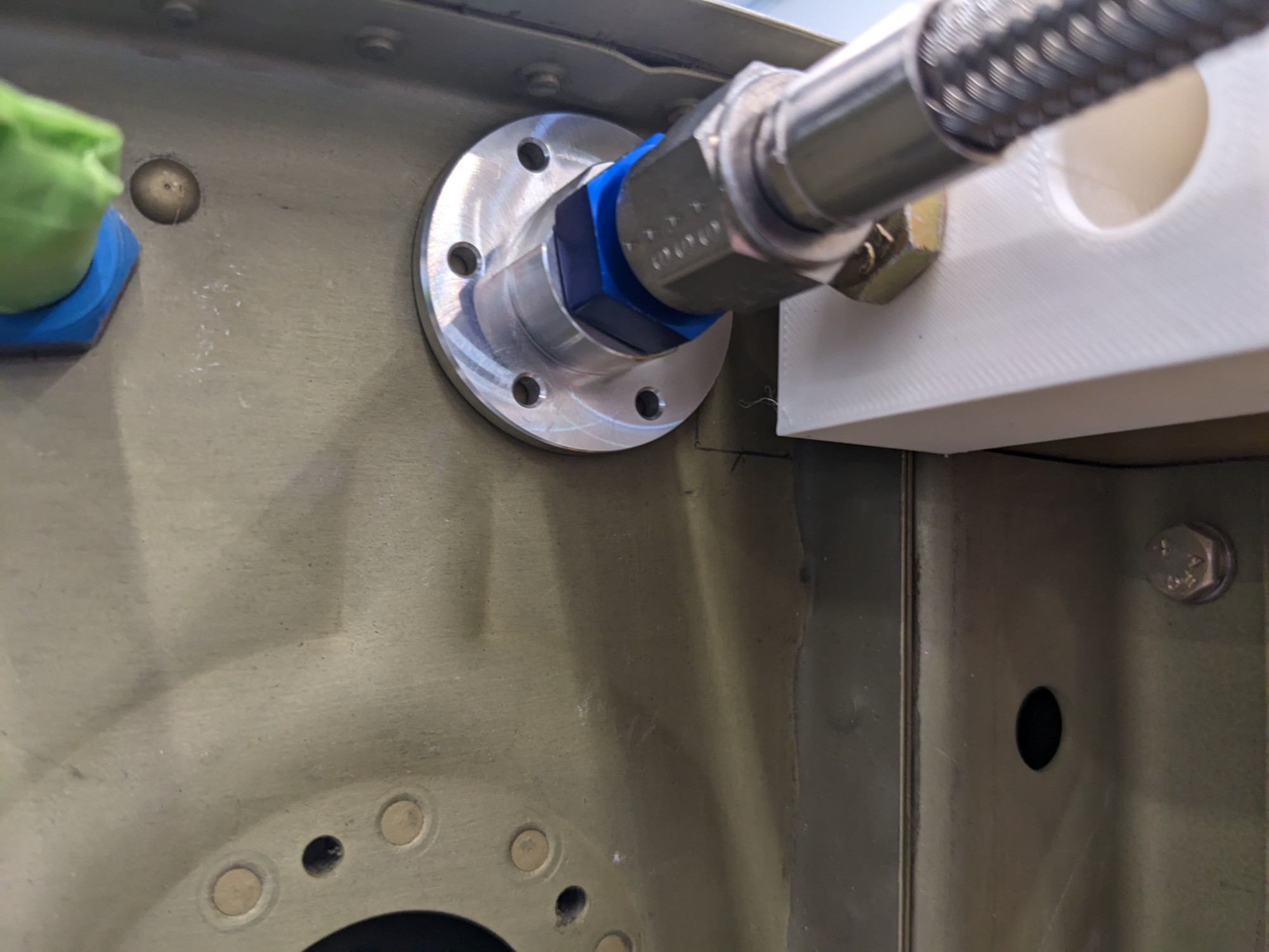
I am using electronic fuel injection (SDS EFI) which requires a return fuel line. I am using the wing root filter kit from Aircraft Specialty Flightlines. The recommended location for the return fuel line is close to the spar. This is especially tight when installing a bung on a quick-build tank, as the bung needs to be installed on the outside.
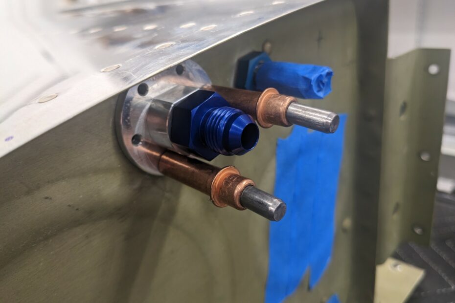
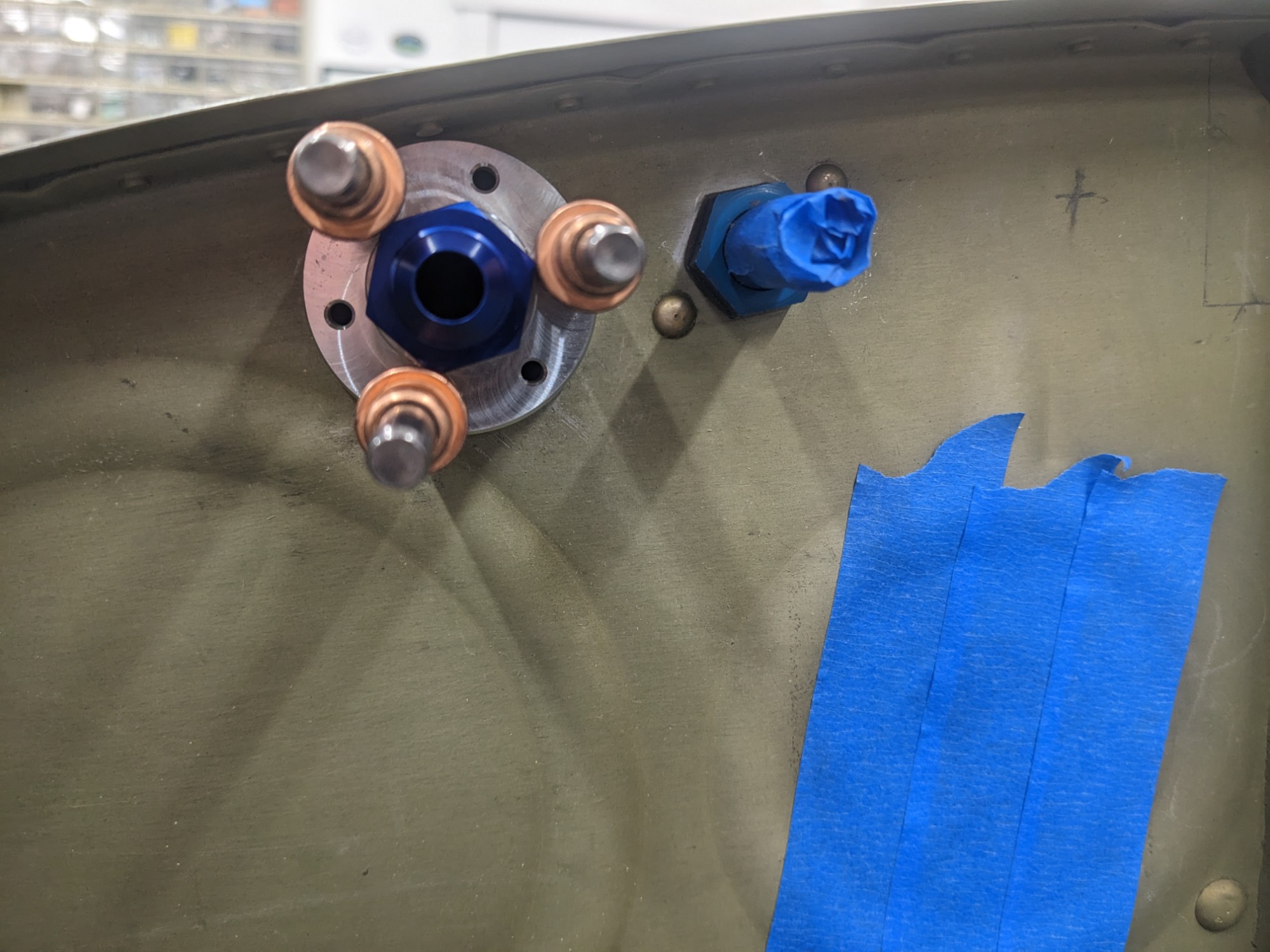
I decided to use the fuel bungs available via FlyEFII as the Van’s fittings are threaded for internal installation only.
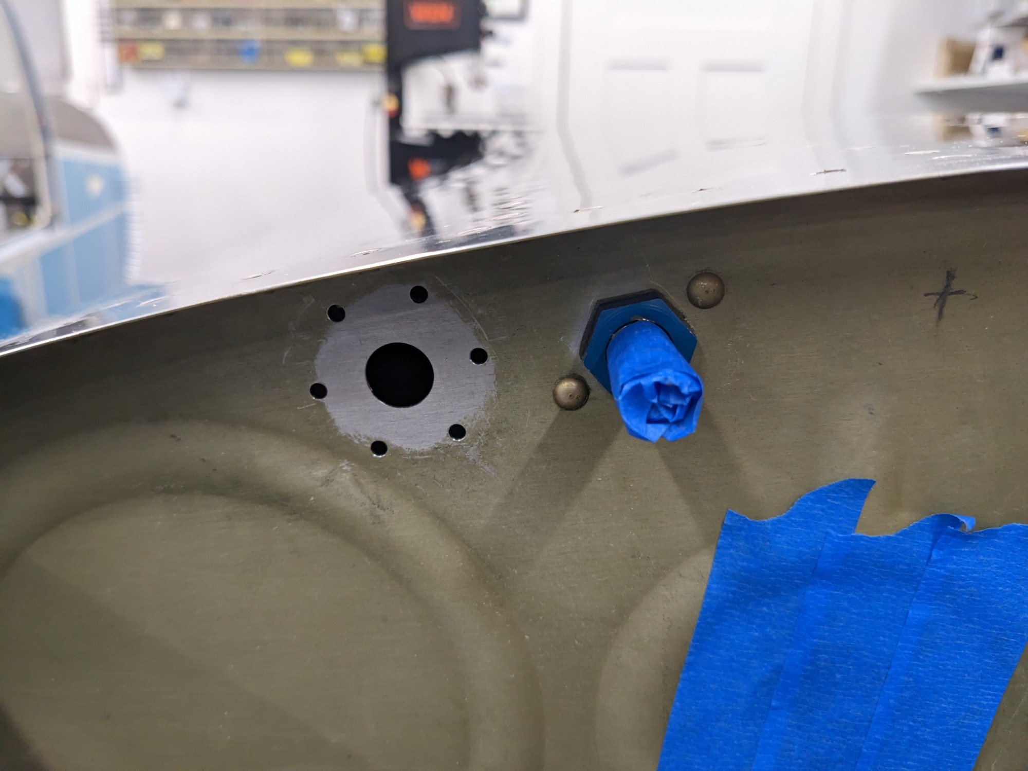
I 3d printed a block to simulate the spar carry-through. There is sufficient clearance at the recommended position (but it doesn’t leave much room) so I ultimately decided to install the bung in a different location (near the vent line).
The location forward of the vent line works well if the bung is clocked to clear the j-channel stiffener inside the tank.
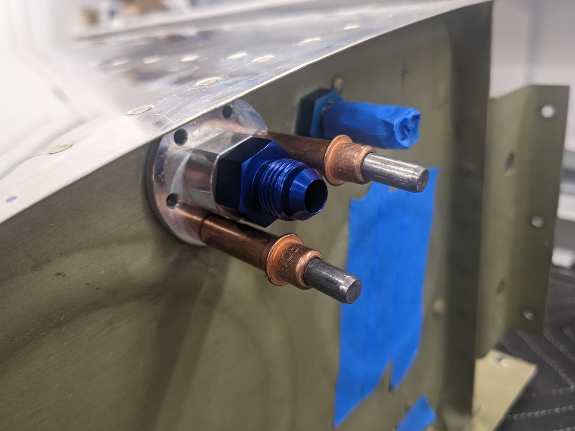
This clocking allows a hole to sit on each side of the j-channel.
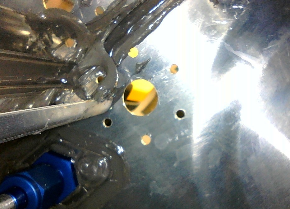
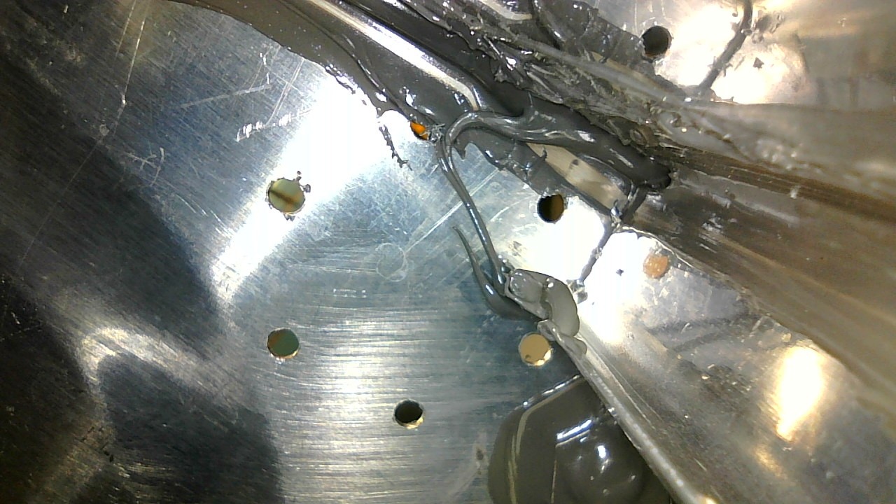
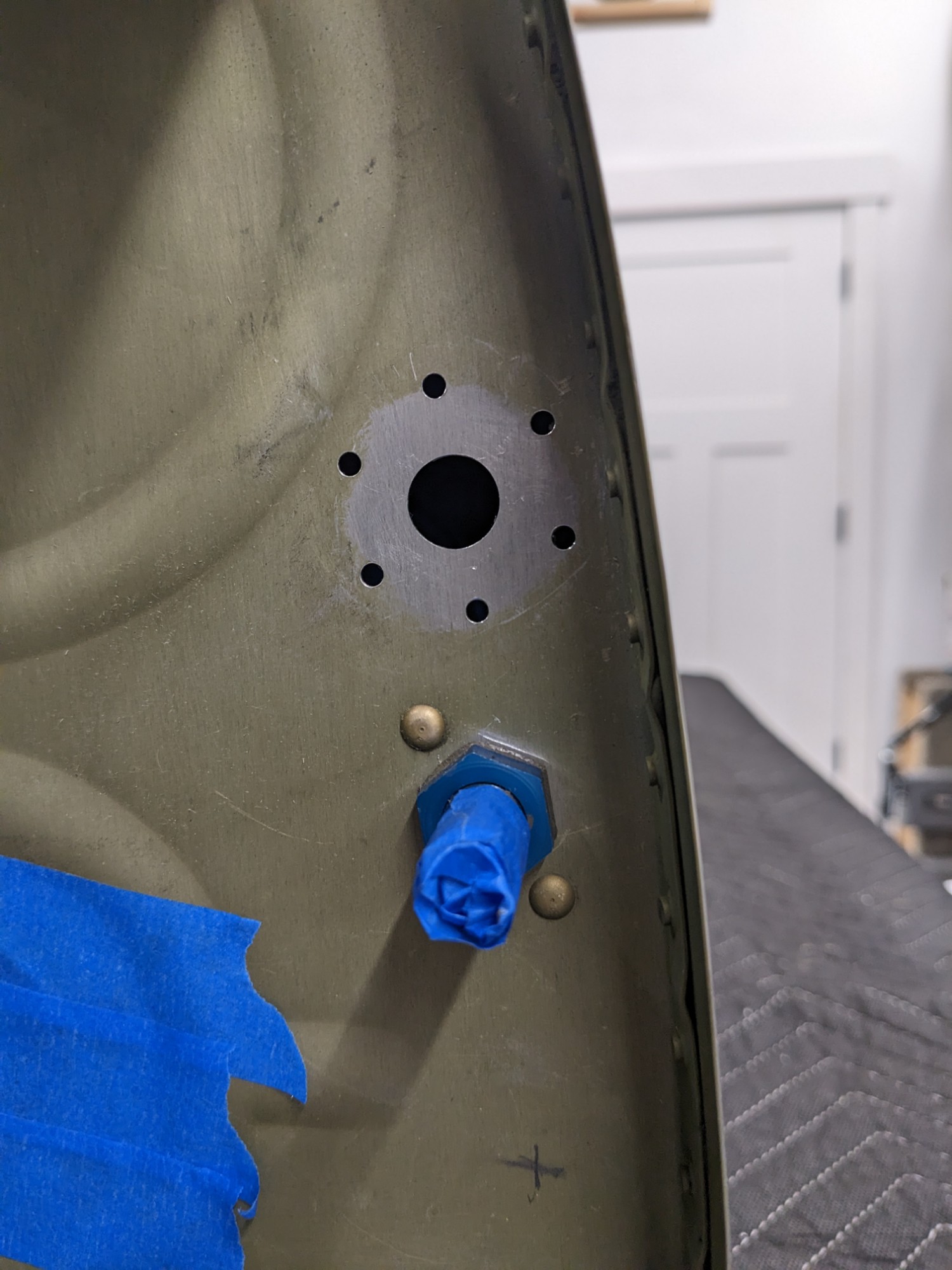
I drilled the holes with grease on the drill bit (and a vacuum in place) but I still got shavings in the tank. I was able to remove these with a vacuum and a borescope.