After a lot of research from other builds, I finally settled on a plan for routing the air conditioning lines.
A primary objective for me in the build is to ensure that systems in the airplane are accessible for inspection and are maintainable and serviceable if I have problems in the future.
One approach I have seen in other builds is to route the A/C lines under the seat floors and into the side walls by punching through the seat ribs. I eventually decided against this approach as it would be difficult to replace a hose if needed in the future (however unlikely – but it is a rubber hose). I will also have a lot of systems running through the sidewalls over the main spar and A/C hoses would add to the clutter (and require two more holes in each of the center section bulkheads along the sidewall).
My preferred approach was to route them via the center tunnel as this would keep everything serviceable and provide a shorter run to the engine-mounted compressor, reducing weight. My tunnel will also be less cluttered than typical builds as my fuel filters will be in the wing roots and I will not need a fuel flow transducer with the SDS EFI.
My remaining (and primary) concern with this approach was the need to punch through the aft bulkhead and the fuselage bulkhead.
In discussing this with Van’s builder support, the answer was as expected: “[paraphrased] You are on your own but multiple builders have done this with no known issues. Make the holes as small as possible, de-burr them well, and maintain edge distance for rivet holes”. In my research (and in discussing with Airflow Systems) I found many others that had routed the lines down the tunnel. This is also the routing that is used by the RV-10 A/C system that is provided by South Florida Sport Aviation (https://www.youtube.com/watch?v=k7id_aLFR5k&t=410s).
Disclamer: I am not an engineer. Modifications to the RV-10 may impact structural strength so please consult an engineer and get any deviations from the plans reviewed if you wish to do something similar. The following documents what I did. This is not provided as guidance or as a recommendation.
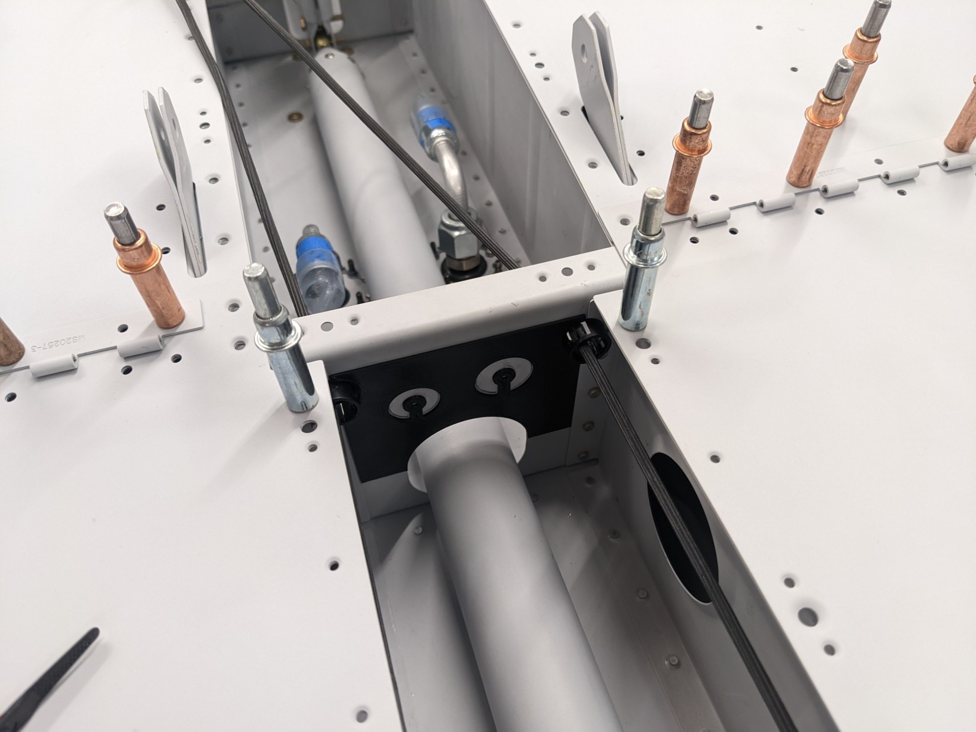
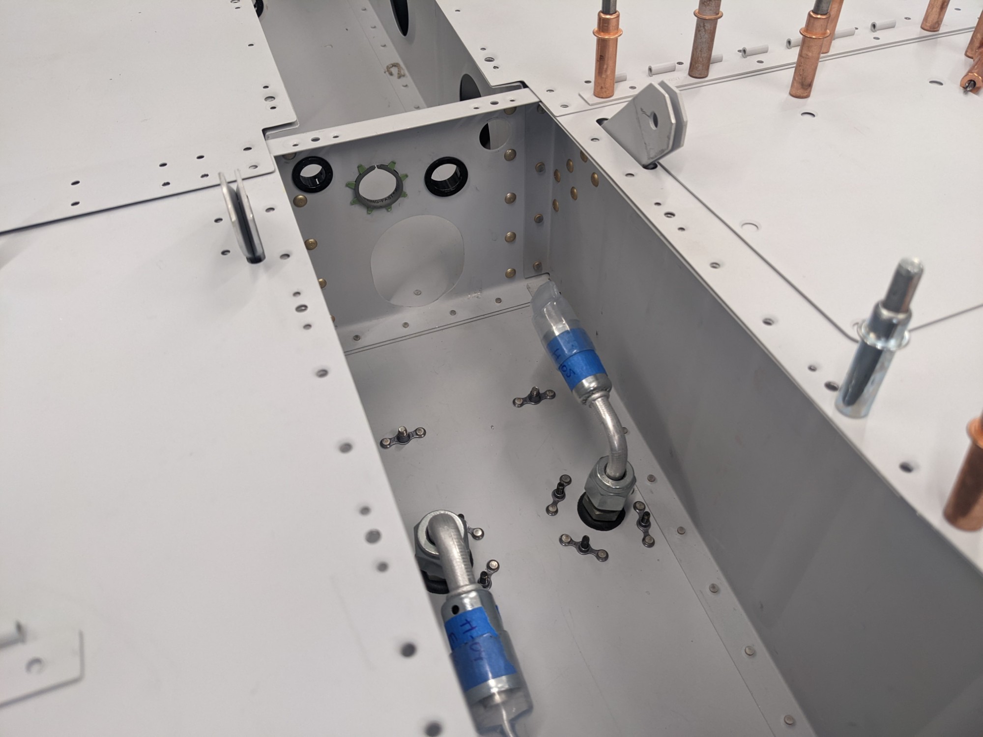
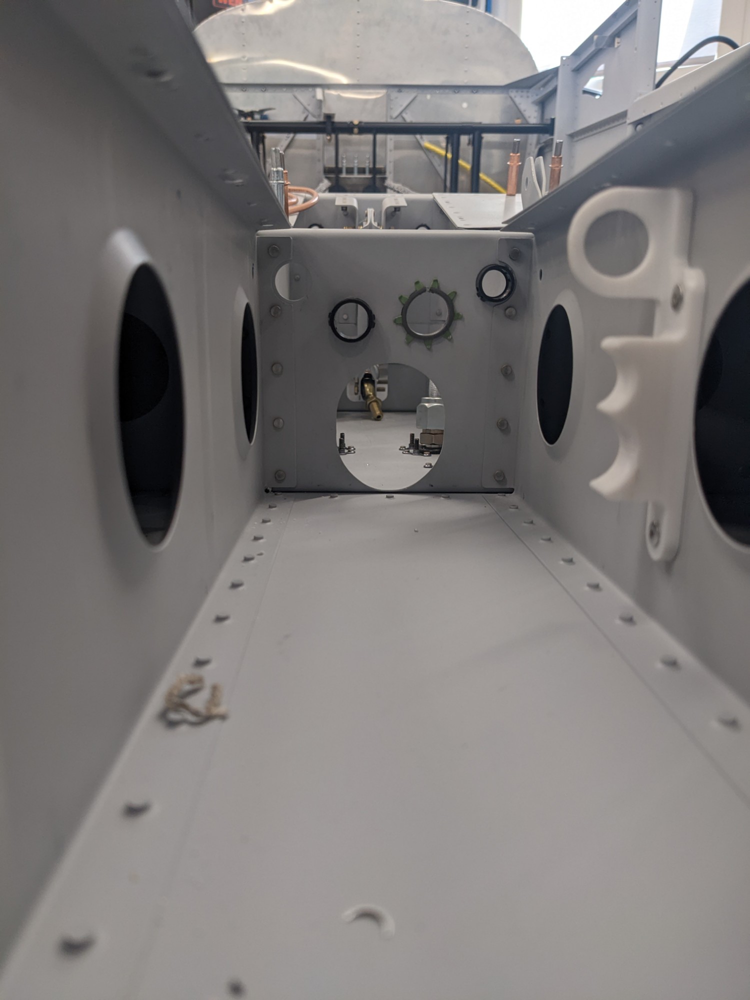
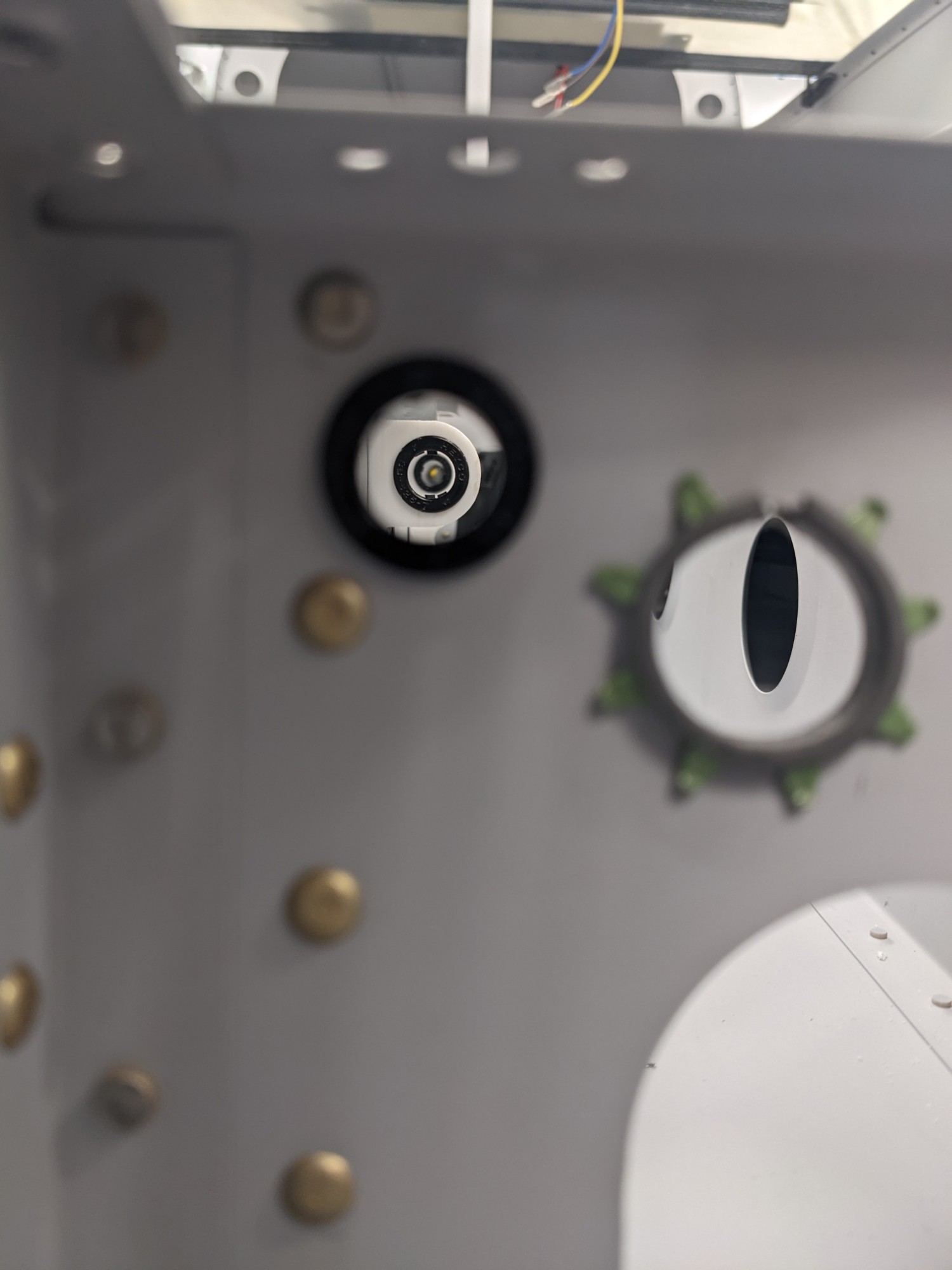
The smaller A/C line fits in a 9/16″ snap bushing and the larger A/C line requires a caterpillar grommet. I decided to sketch a drilling template in OnShape and I used constraints to maximize the spacing between all holes (from the rudder cable holes and the pushrod hole). This gave me the maximum possible distance from every hole to every other hole. The picture below shows the 3d printed template snapped into place prior to drilling. I made the final holes as small as possible to snugly fit the bushing and grommet.
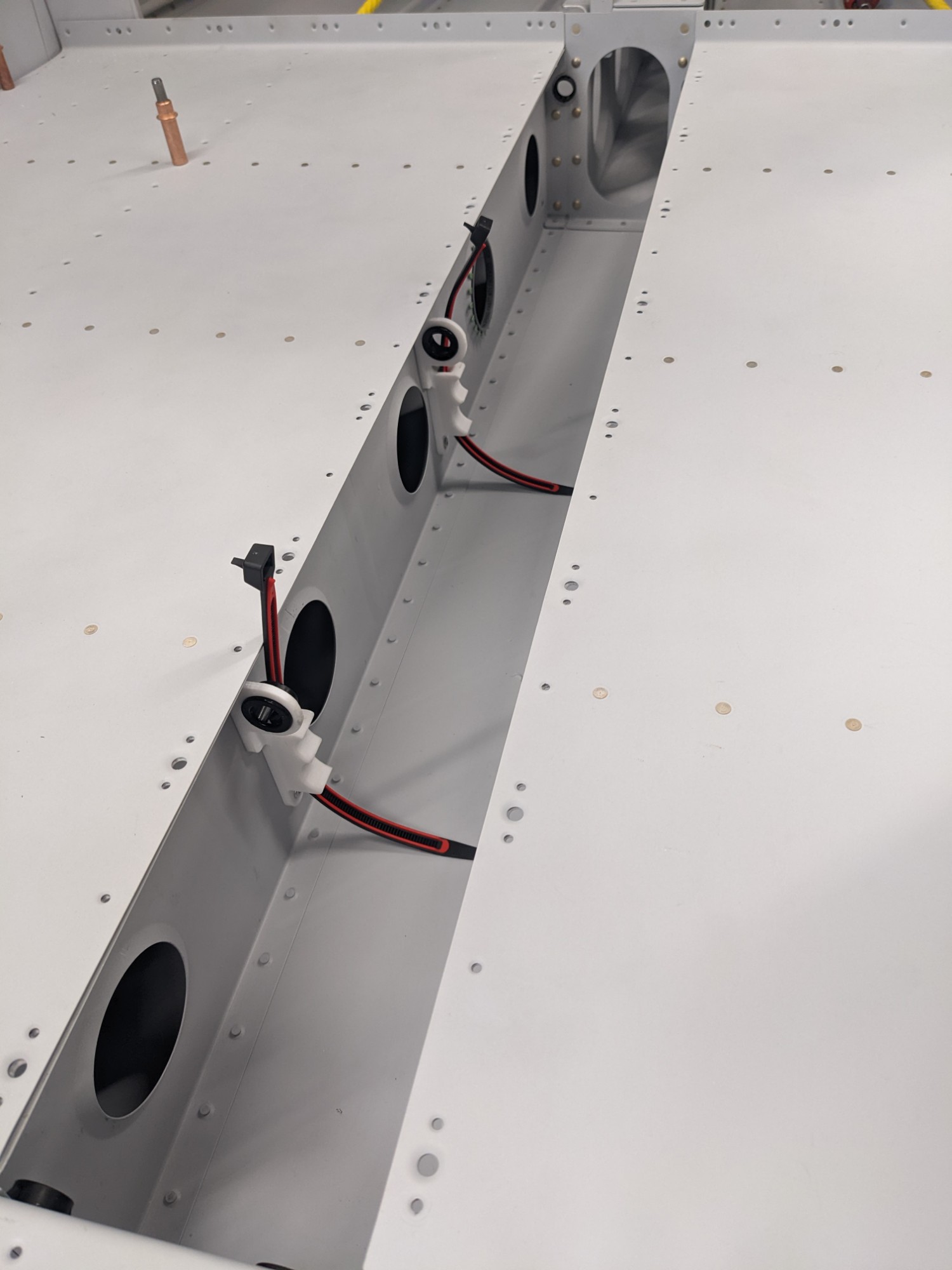
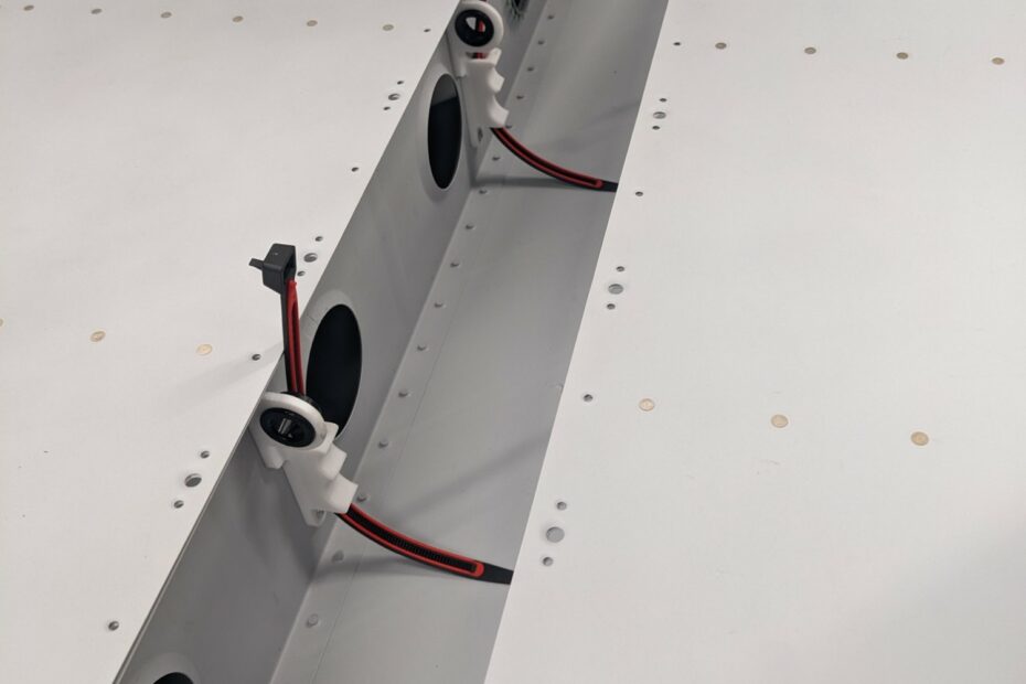
To secure the lines in the tunnel aft of the fuselage bulkhead, I 3d printed some polycarbonate brackets that will allow me to secure the hoses along the right wall of the tunnel. This gives me plenty of clearance from the pushrod (I don’t have a picture of that in place as I forgot to take one before I removed the pushrod to rivet the brackets into place. I’ll loop back and add pictures when the push rod is re-installed later).
I designed clips into the brackets for inserting snap bushings to guide the rudder cables and avoid any potential for them to interfere with the A/C lines or the brackets.
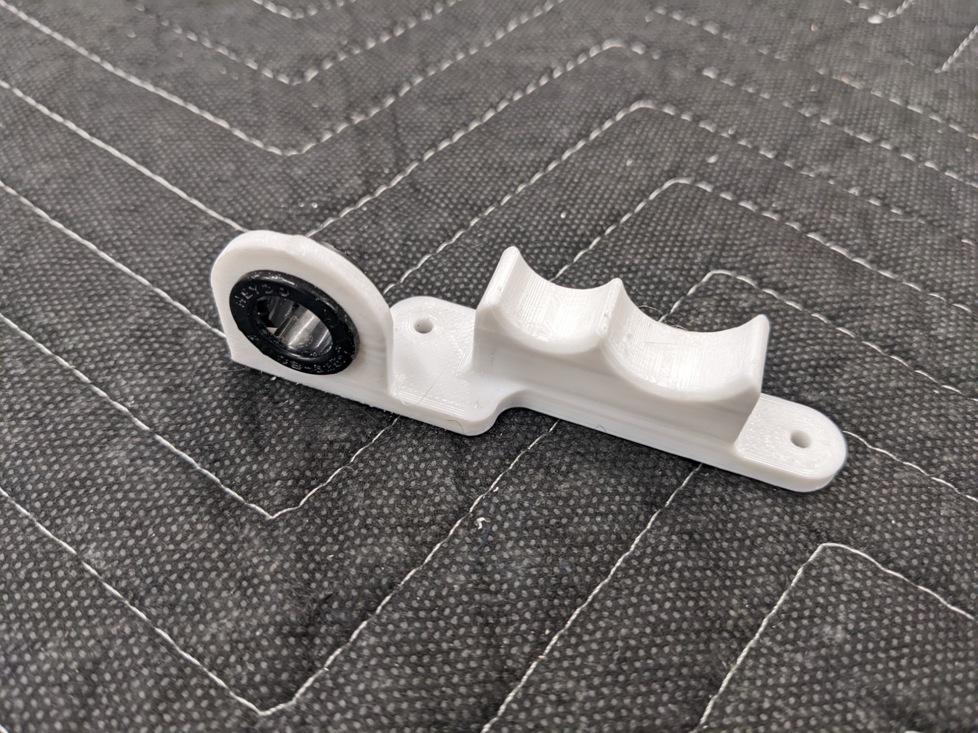
The bushing holes were designed to align with the stock bushings so that there is no lateral tension on the rudder cable.
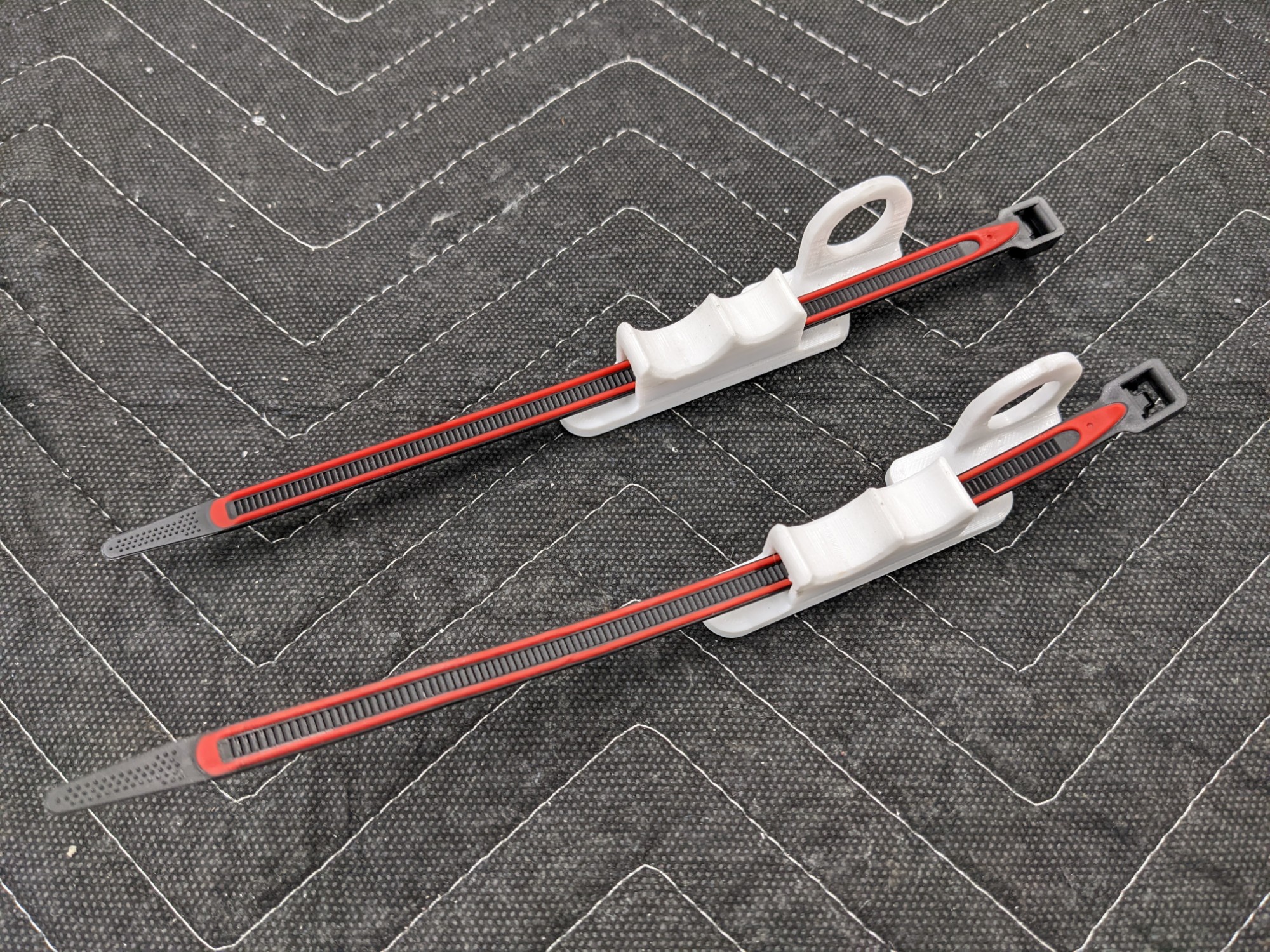
The A/C hoses secure tightly to the brackets using Grip Lock Ties and will be routed into the tailcone via the aft-most lightening hole on the right side of the tunnel (left in this photo as it is taken looking aft).