Before riveting the bottom skins into place I decided to make the brackets for mounting the PH Aviation Flap Actuator. The supplied plans provide drawings for making custom brackets as the actuator is not a drop-in replacement. I generally followed the plans but I had to make some modifications as noted below to make things fit.
This process was simple enough but it ended up taking way longer than I had anticipated. I am learning pretty quickly about the impact of mods on build time…
I ordered the following from Aircraft Spruce:
- 1x AN5-23 bolt
- 1x AN310-5 castle nut and cotter pin
- 4x AN960-516L washer
- 2x AN960-516 washer
- 1′ 2024T3 Angle 1x1x1/16
- 2′ 2024T3 Angle 1.5×1.5×1/16 (I didn’t need 2′ but wanted some extra for other brackets that I might need to make along the way)
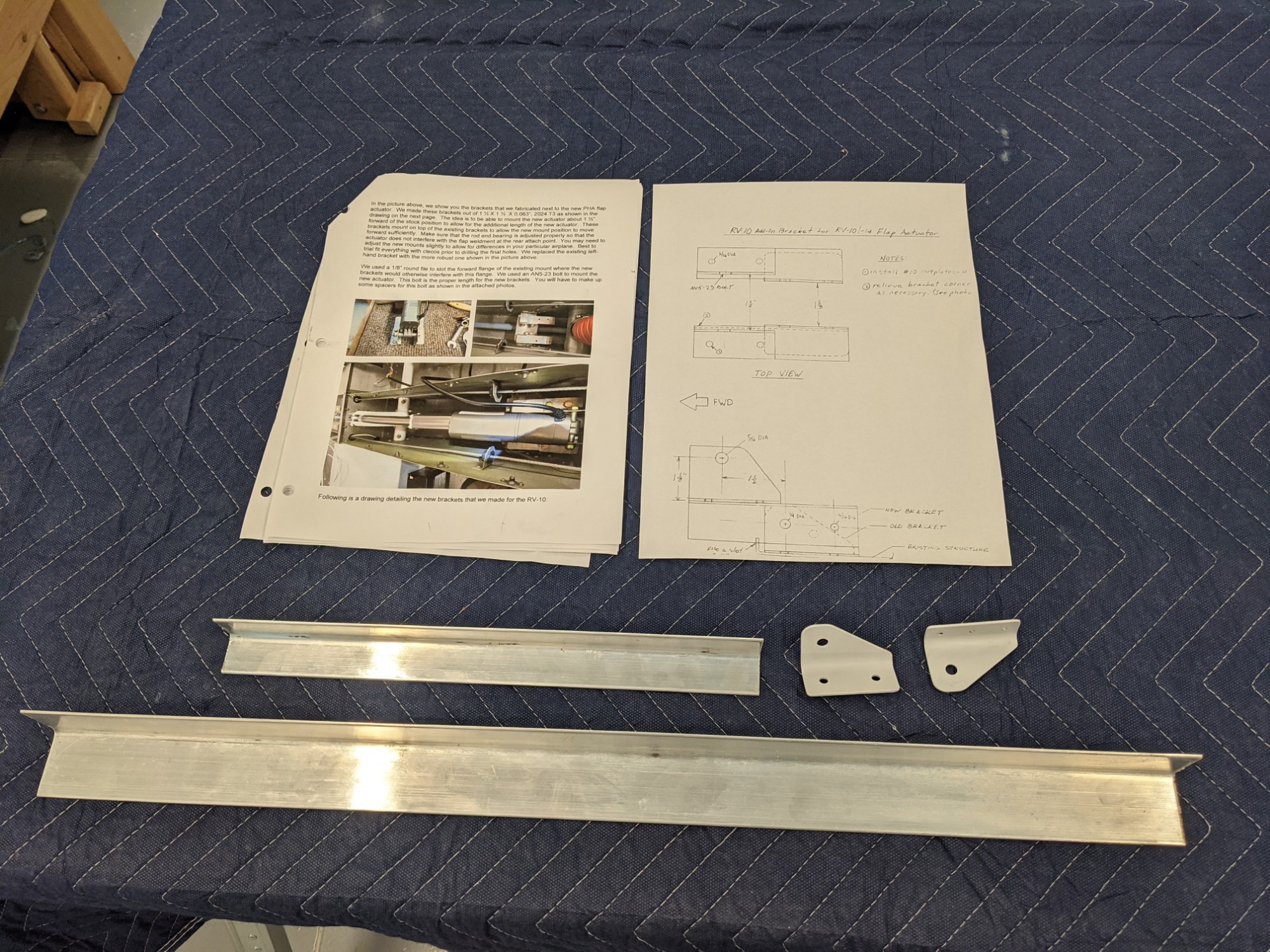
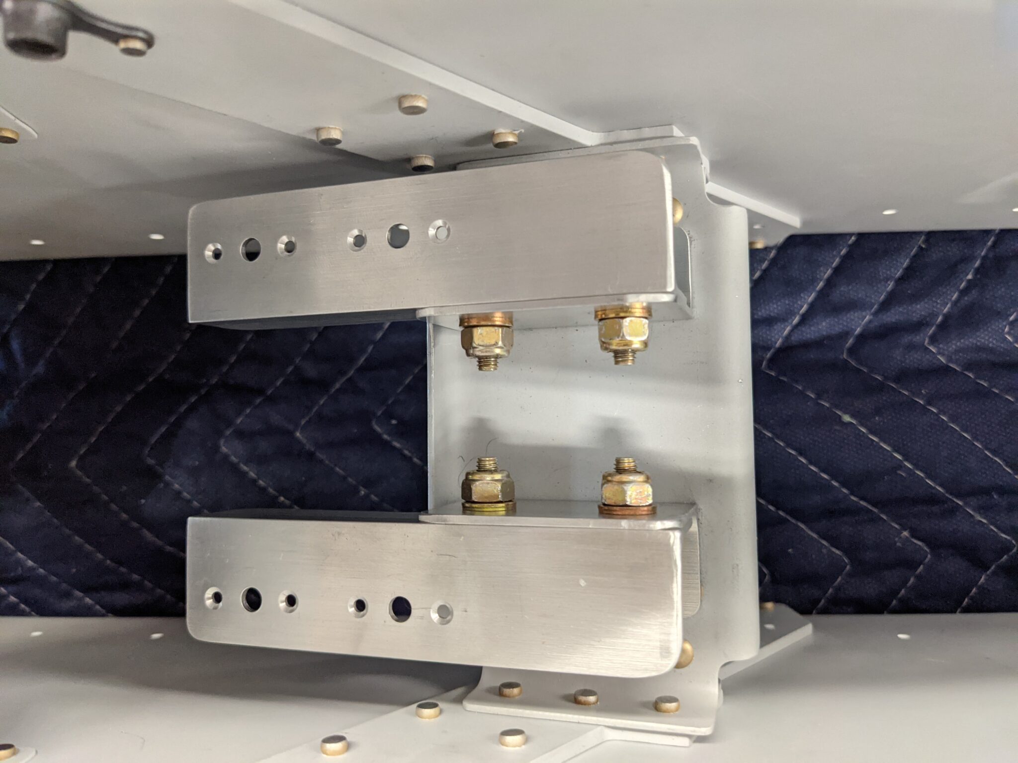
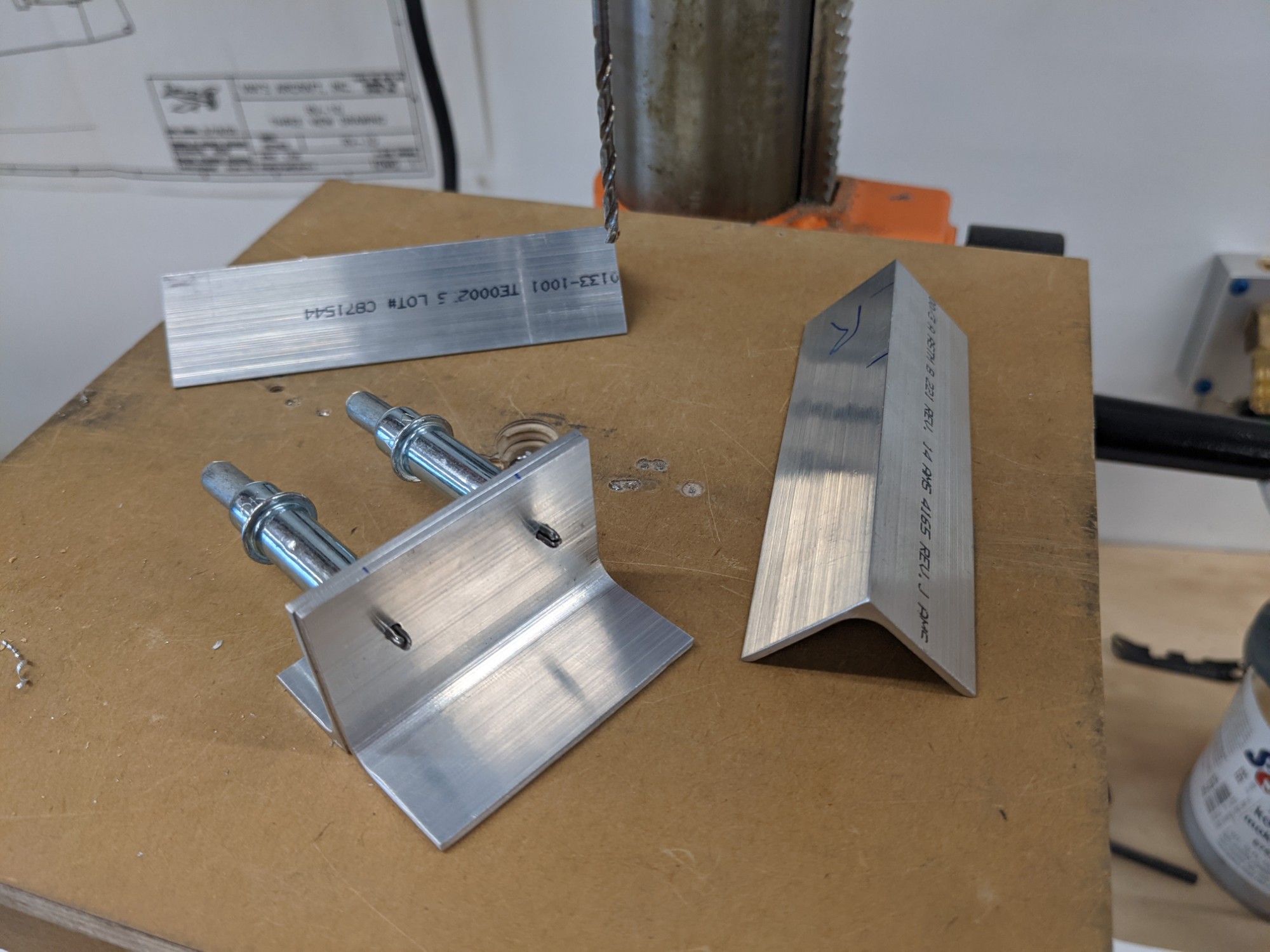
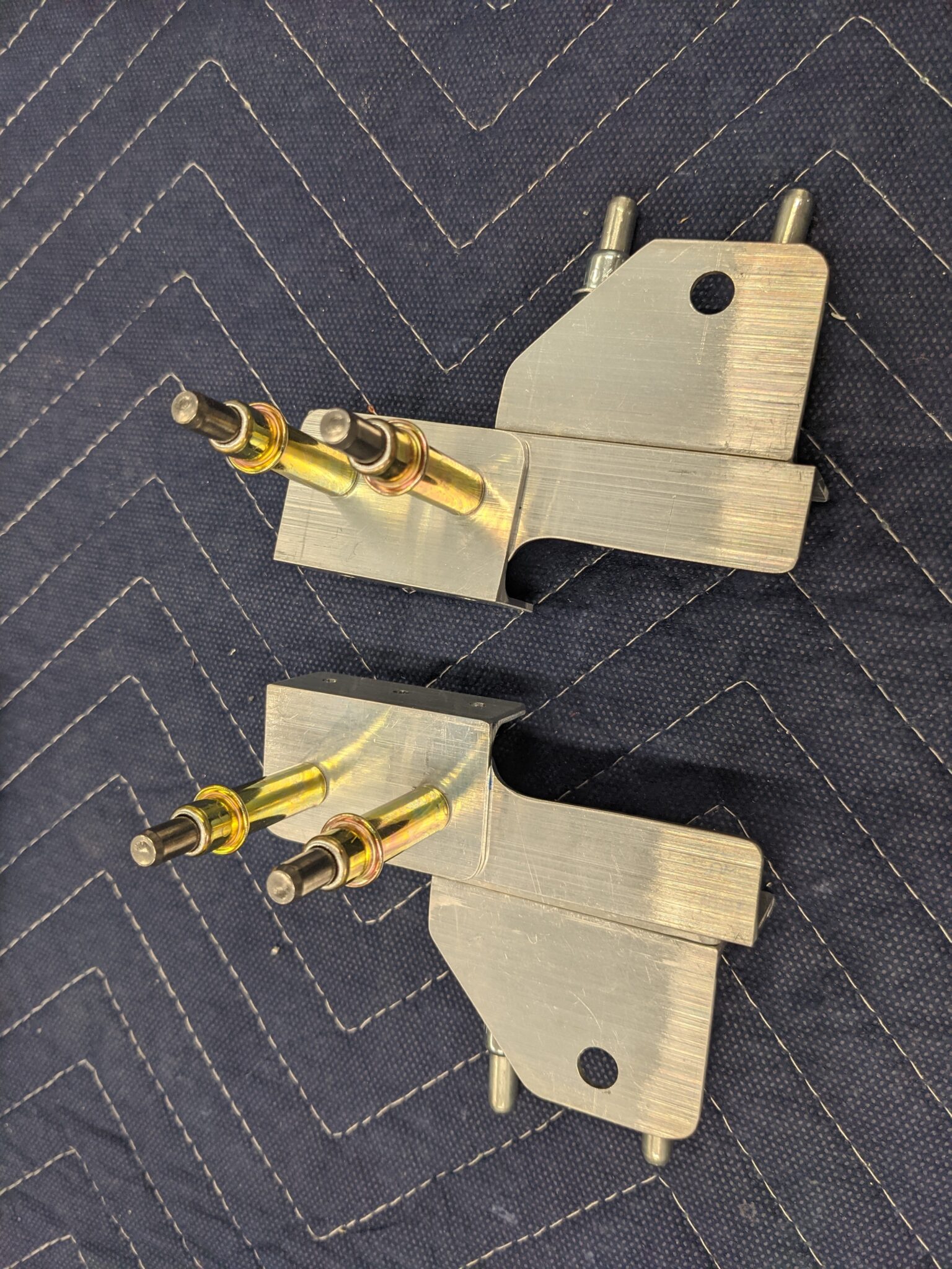
I didn’t use the stock brackets (on the top right above) and instead made replacement brackets for both so that I could have two bolts in each. The bolts attach the 1″ aluminum angle extensions to which the actuator brackets are mounted.
First up was cutting the parts to size and marking and drilling the necessary holes. I got busy here and didn’t take many pictures.
The stock brackets aren’t centered in the tunnel. The right bracket is riveted and the left uses bolts which results in different edge distances on each side. I attached my new brackets to the stock holes and then bolted them temporarily into place. I used three washers on the bolts that thread into the nutplates as I didn’t want to seat these fully yet.
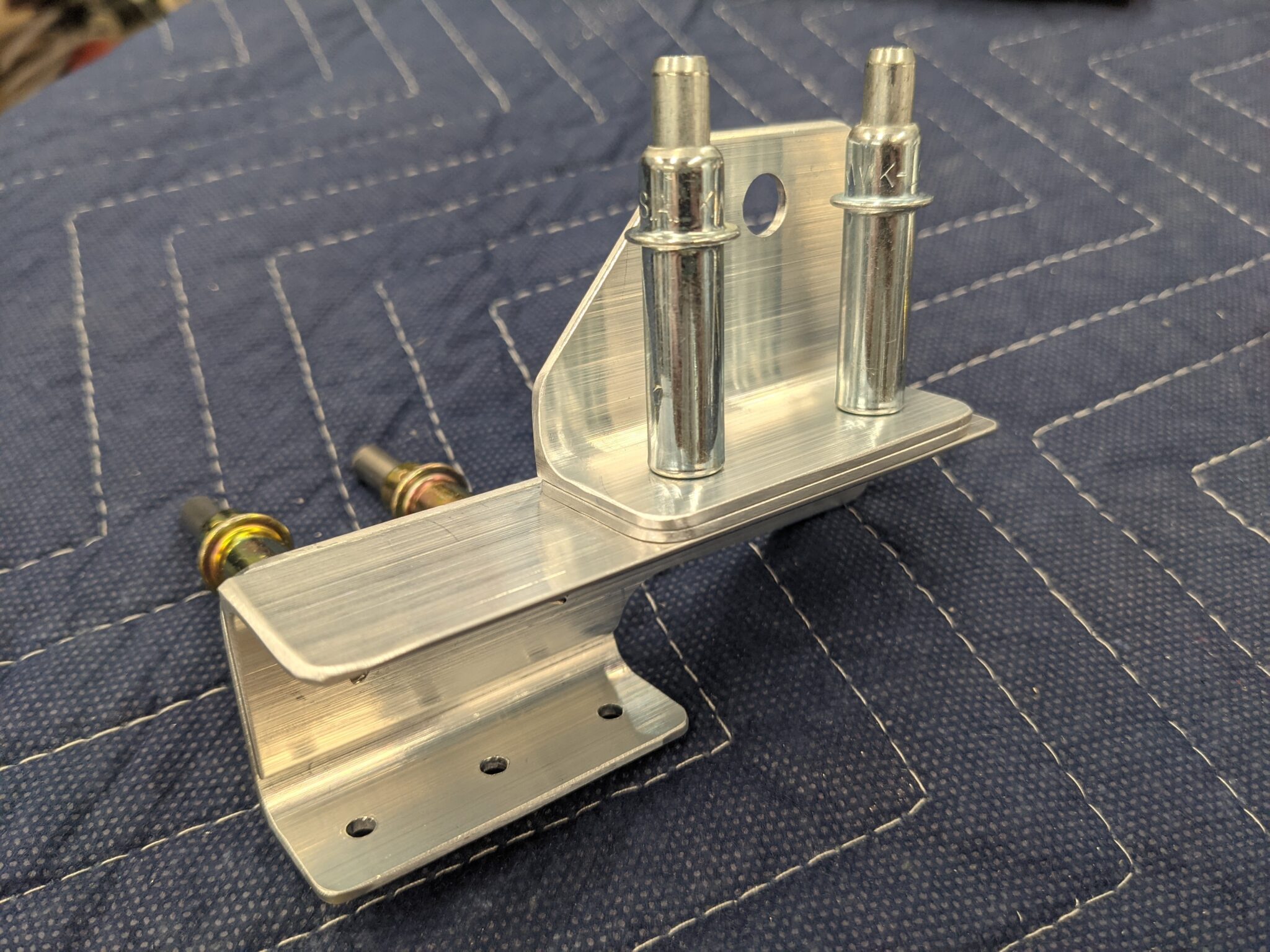
The provided plans call for filing the forward flange of the stock mounting plate to make room for the angle. It would have required a decent sized notch so I chose instead to shape the aluminum angle to allow it to pass over the flange. This leaves 3/4″ of material (pics below).
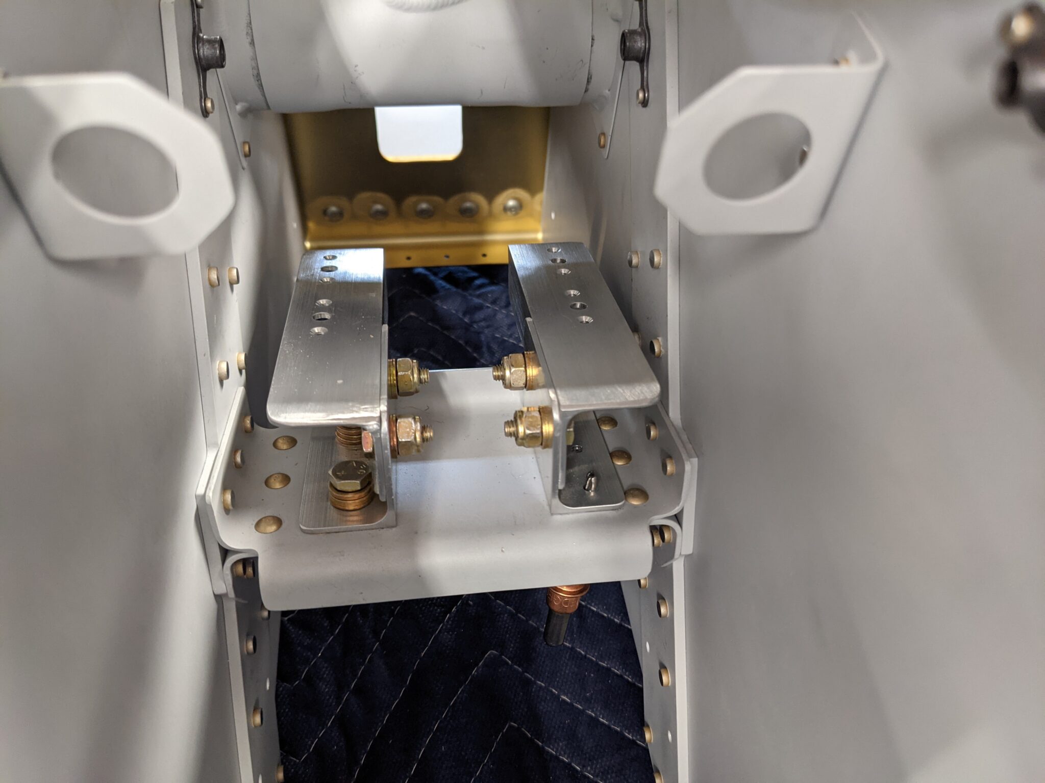
I then bolted the 1″ angle extensions to the brackets. It was a little tricky to reach the back of the bolts and it won’t be possible to get a torque wrench between the two brackets. I’ll have to find some other way to torque these during the final install.
To get the lateral positioning correct I decided to attach the forward brackets to the mounting plate first and then align things in the tunnel. The gap between the forward brackets and the actuator pivot point is 1/2″ on each side. My plan was to use two 1/2″ spacers with 4 thin washers. That would give me 1/16″ of clearance from the brackets to the actuator housing.
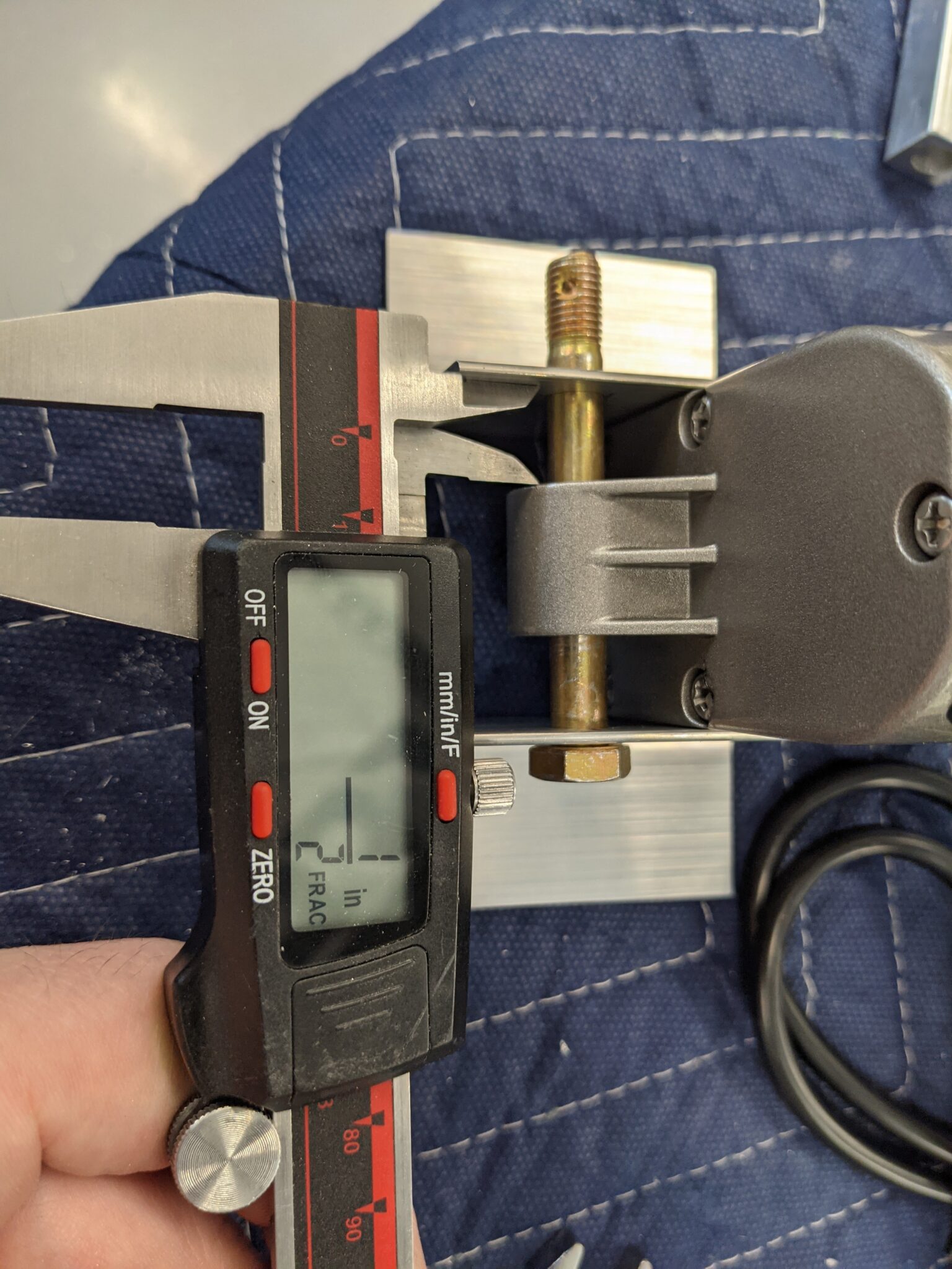
At that point, I realized that I had mistakenly assumed that I could use the spacer material from the stock actuator but that is sized for an AN4 bolt, not an AN5.
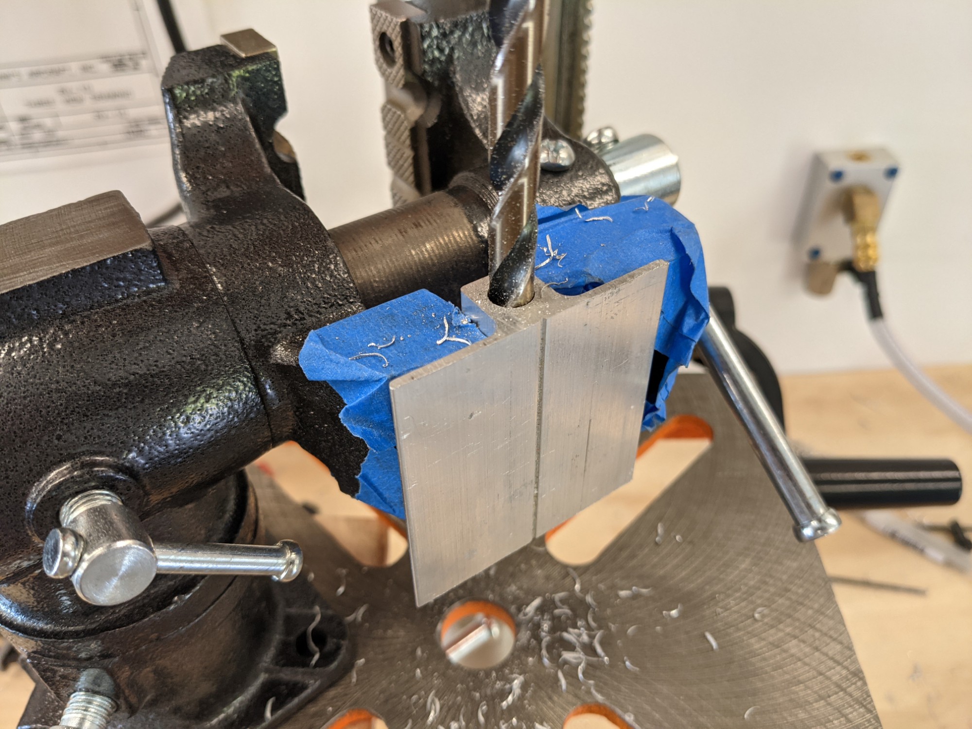
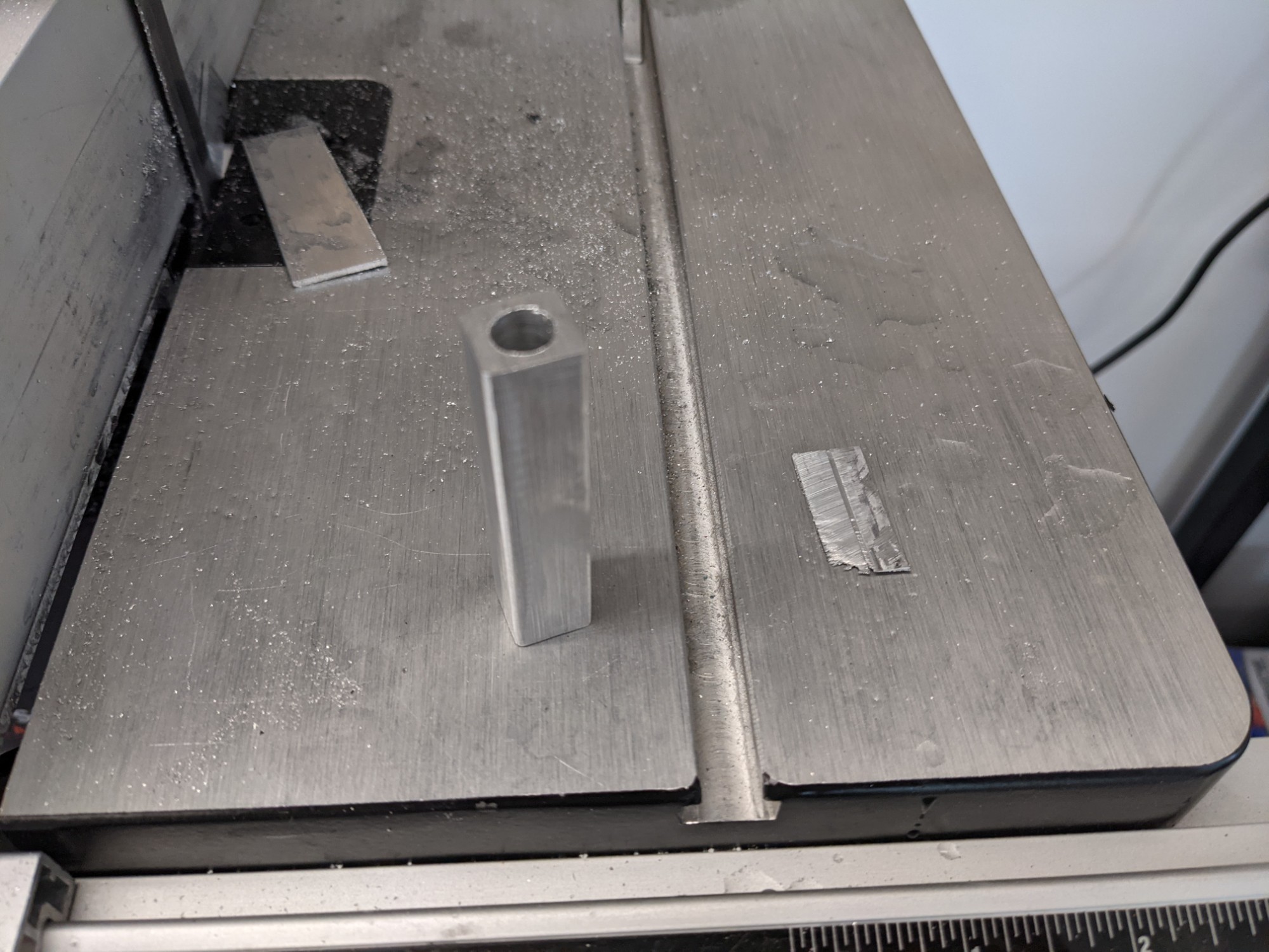
I didn’t want to wait for another order so I dug through my scraps and decided that I could make suitable spacers from the remnants of the tailcone tie-down block.
I drilled out the hole to 5/16″ in the drill press and trimmed off the edges on the bandsaw.
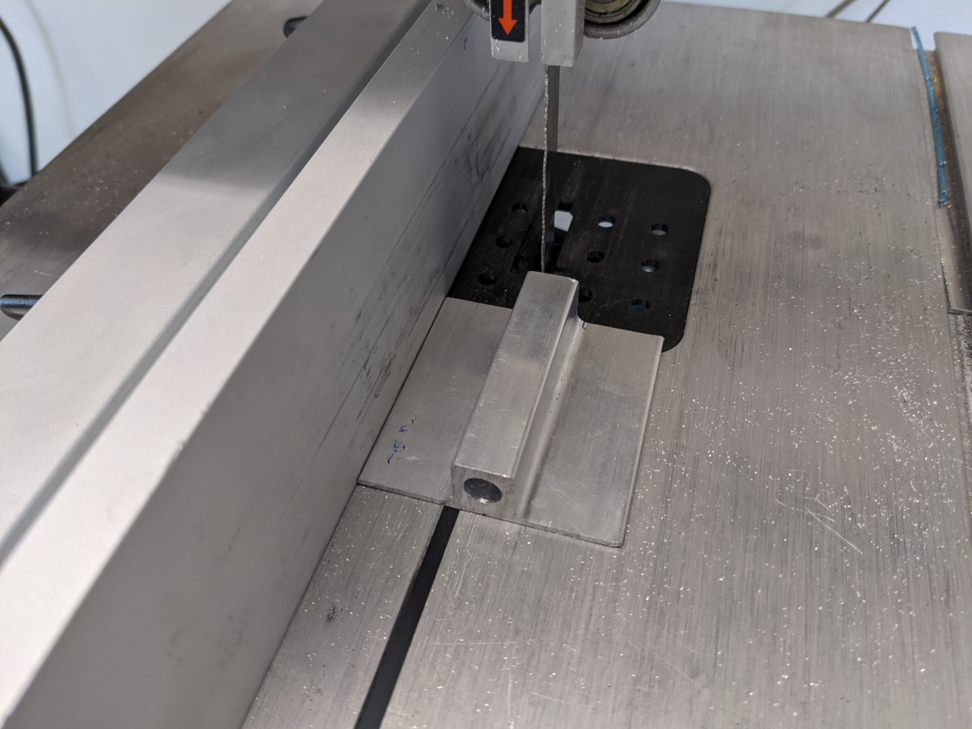
I then squared off the bottom edge as the material is thicker on this side.
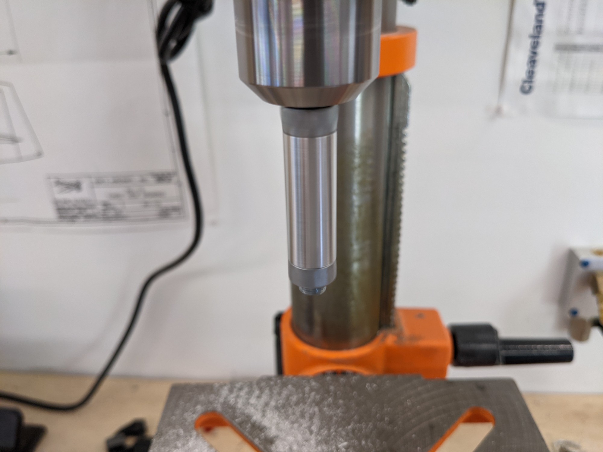
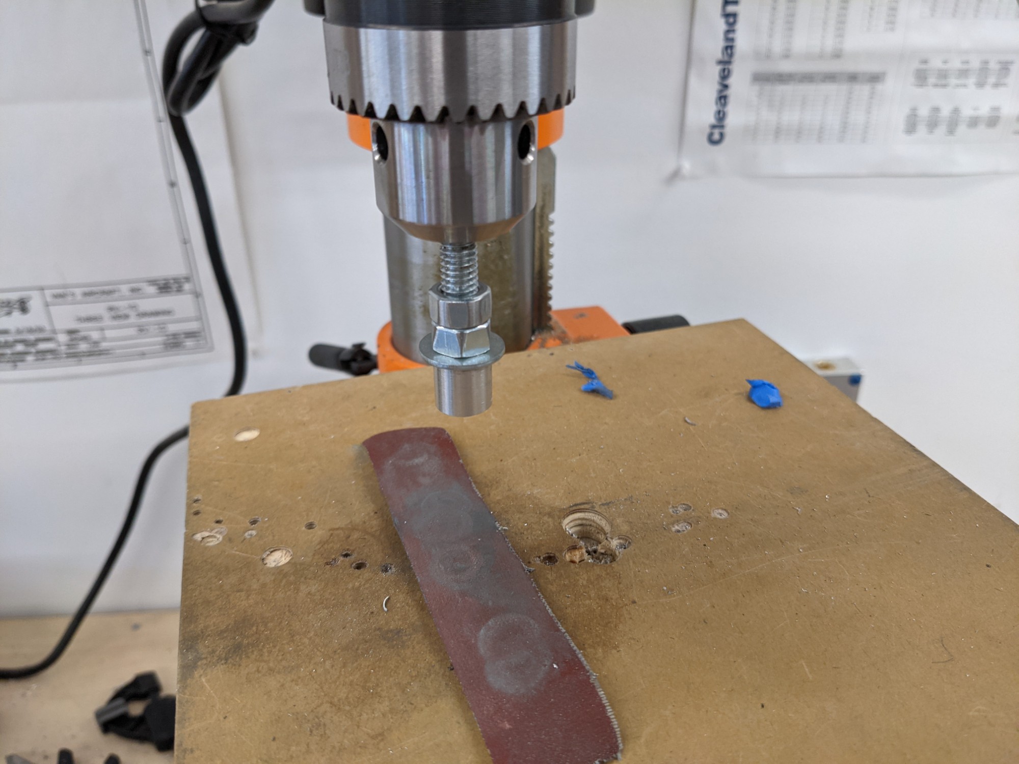
I rough-sanded the corners on the belt sander and then chucked it in the drill press between two bolts on a threaded rod. This makeshift lathe worked well (albeit slowly as I didn’t want to put too much side pressure on the chuck). I used a vixen file to remove the bulk of the material and emery paper to finish it.
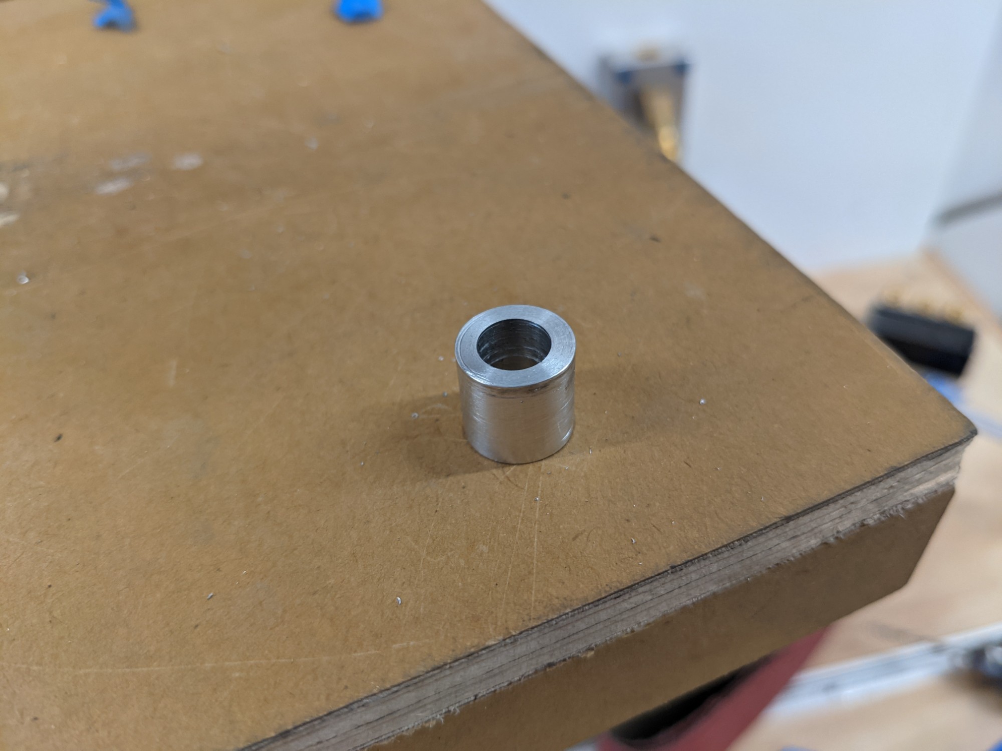
I then cut the lengths that I needed and sanded them to the final size on the drill press. This kept everything square without needing a lathe.
Success. Onwards.
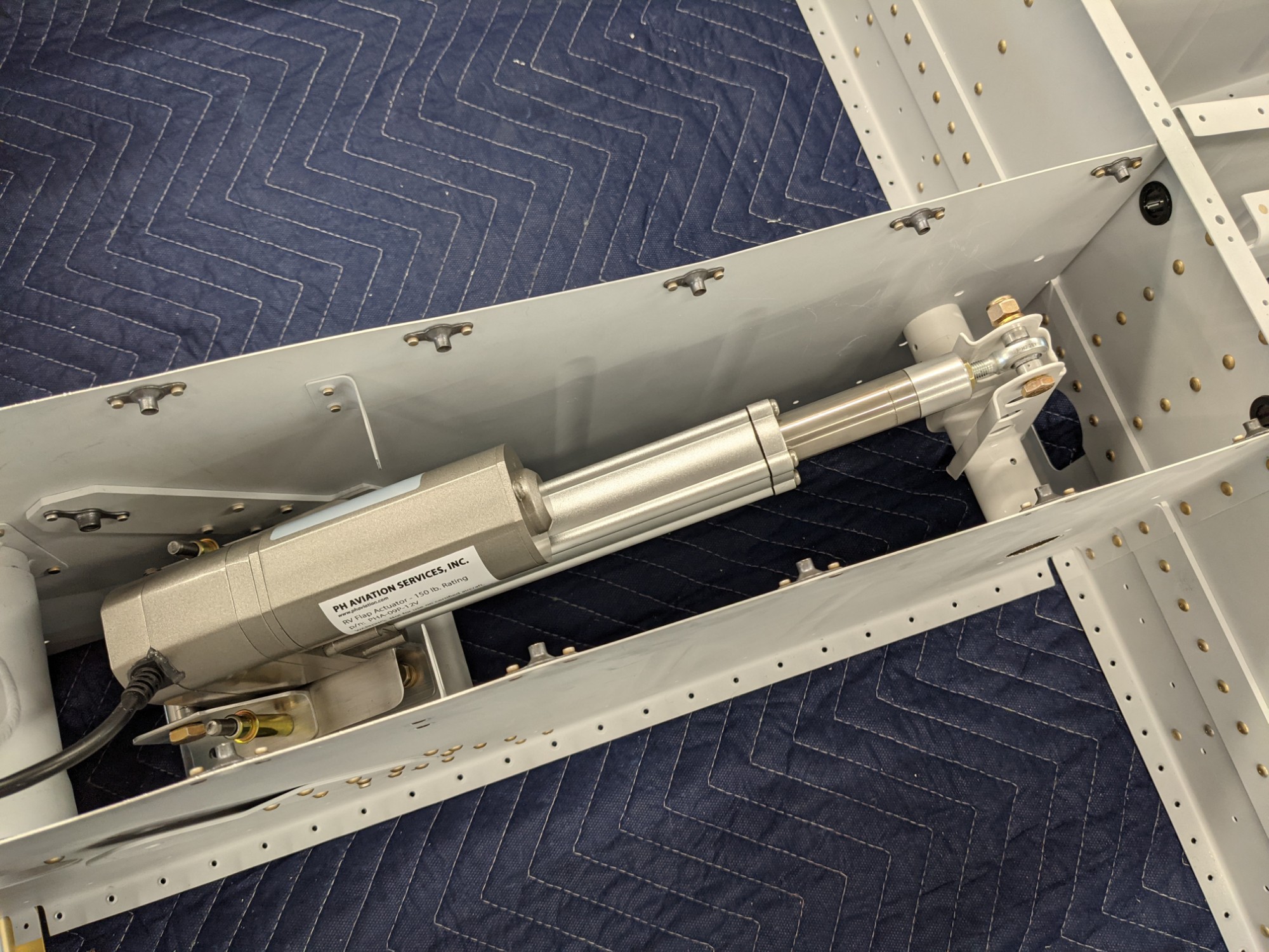
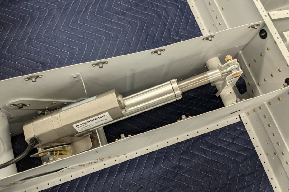
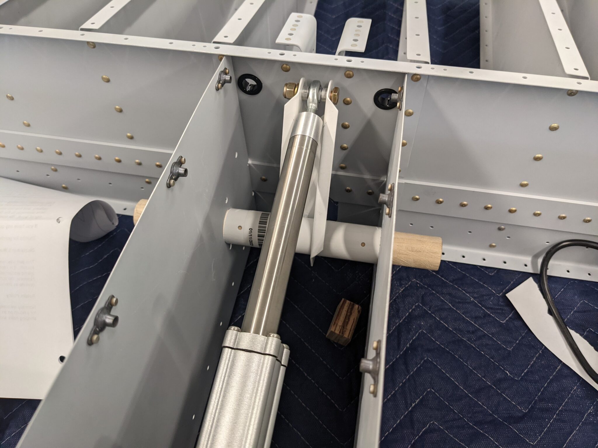
Everything fit together nicely with the intended clearance on each side.
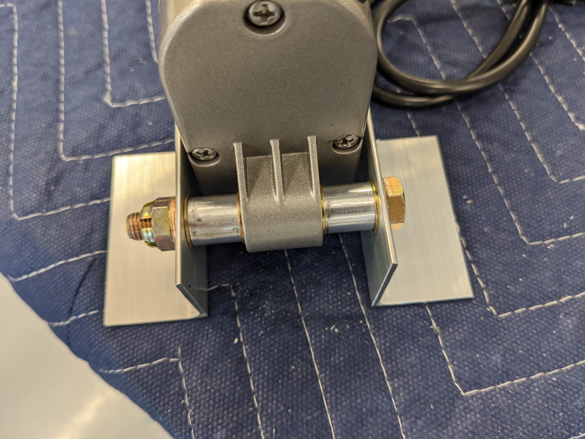
I mounted the actuator to determine the lateral alignment and to double-check the travel. I then marked and drilled the pilot holes for attaching the actuator attach brackets to the extensions. I left the extensions a little long to make room for nutplates (with appropriate edge distance for AD3 rivets). The provided plans don’t leave much room here and the pictures accompanying the plans show some creative nutplate placement.
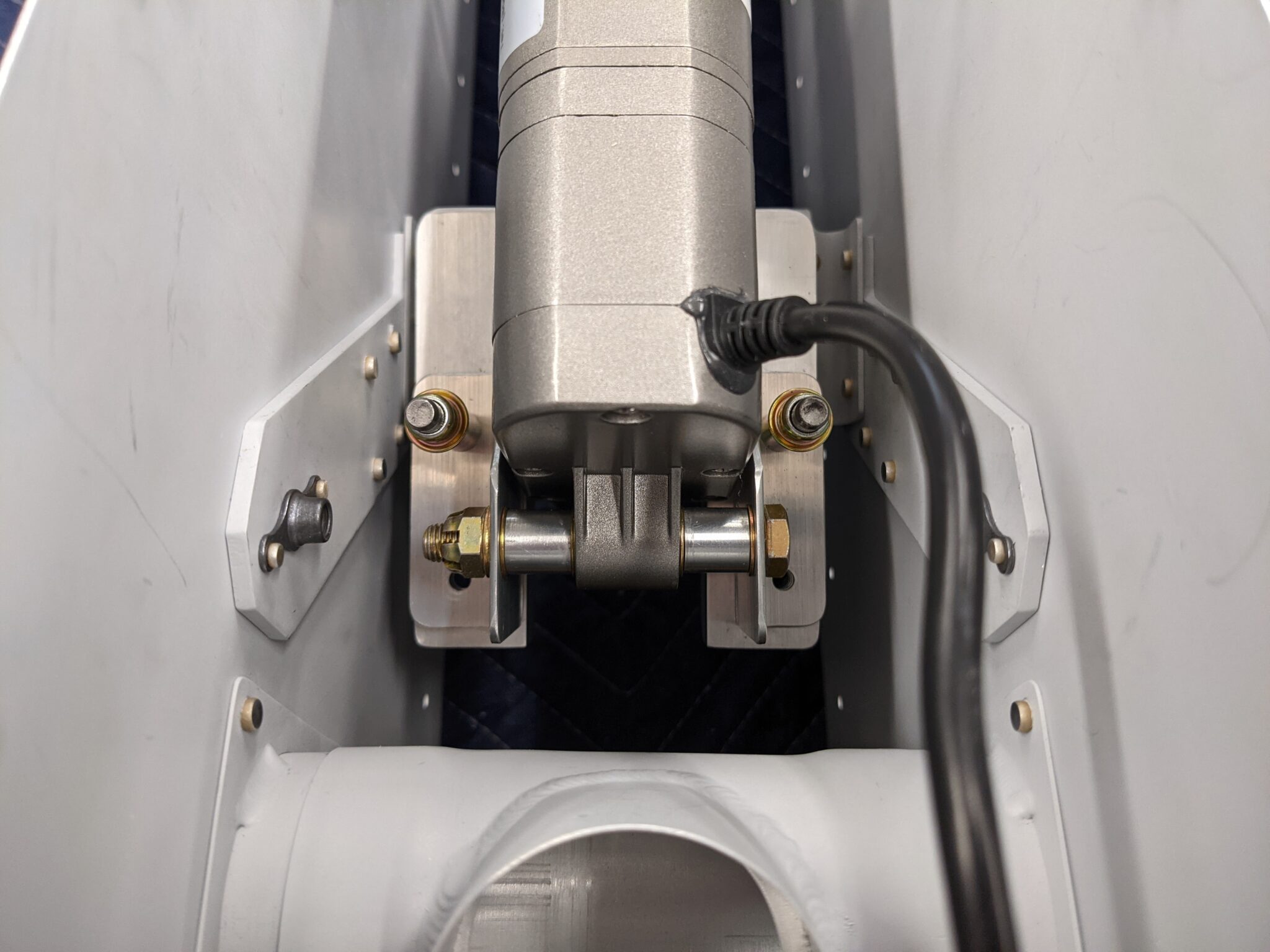
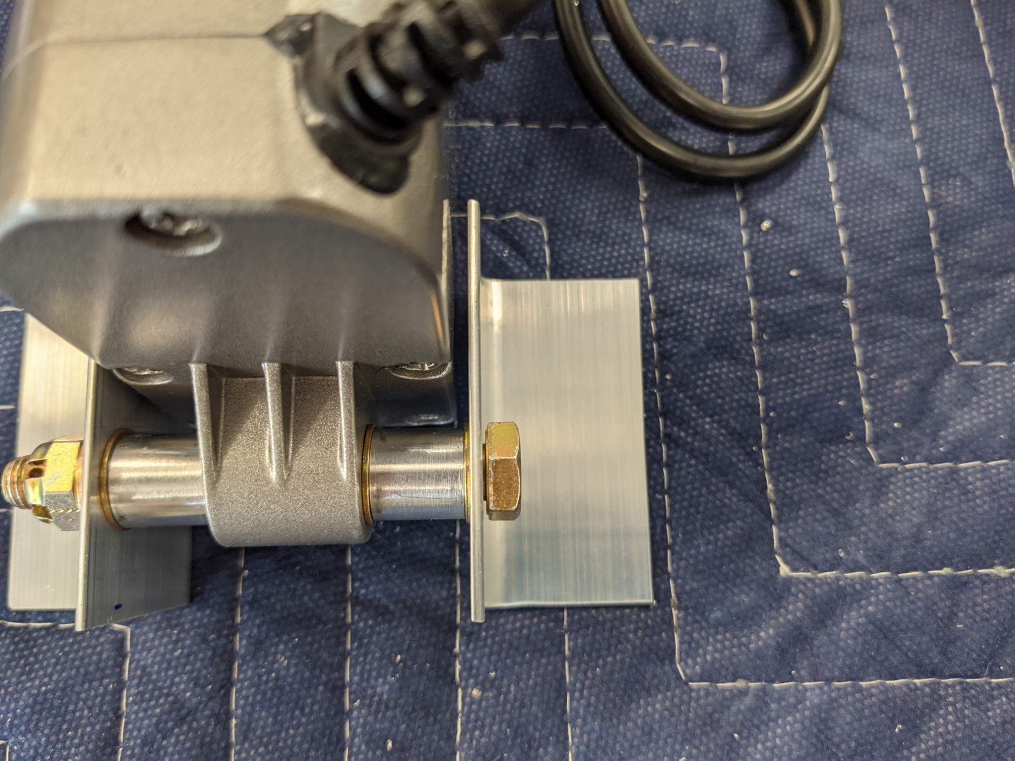
Everything aligned well but the bottom of the actuator housing touches the aft part of the aluminum extensions when at full extension. I tried rounding the extensions a bit but I determined that I was going to need at least 1/8″ of extra clearance to make it work. It also isn’t as simple as rounding the most forward part of the extensions as the actuator case hits about 1/2″ back from the front of the brackets. There also isn’t enough edge distance in the 1.5″x1.5″ angle to move the AN5 bolts any higher so I ended up making two spacers to lift both brackets by 1/8″ (I tried one spacer first, reassembled, still no dice, disassembled, made another set of spacers, reassembled, success).
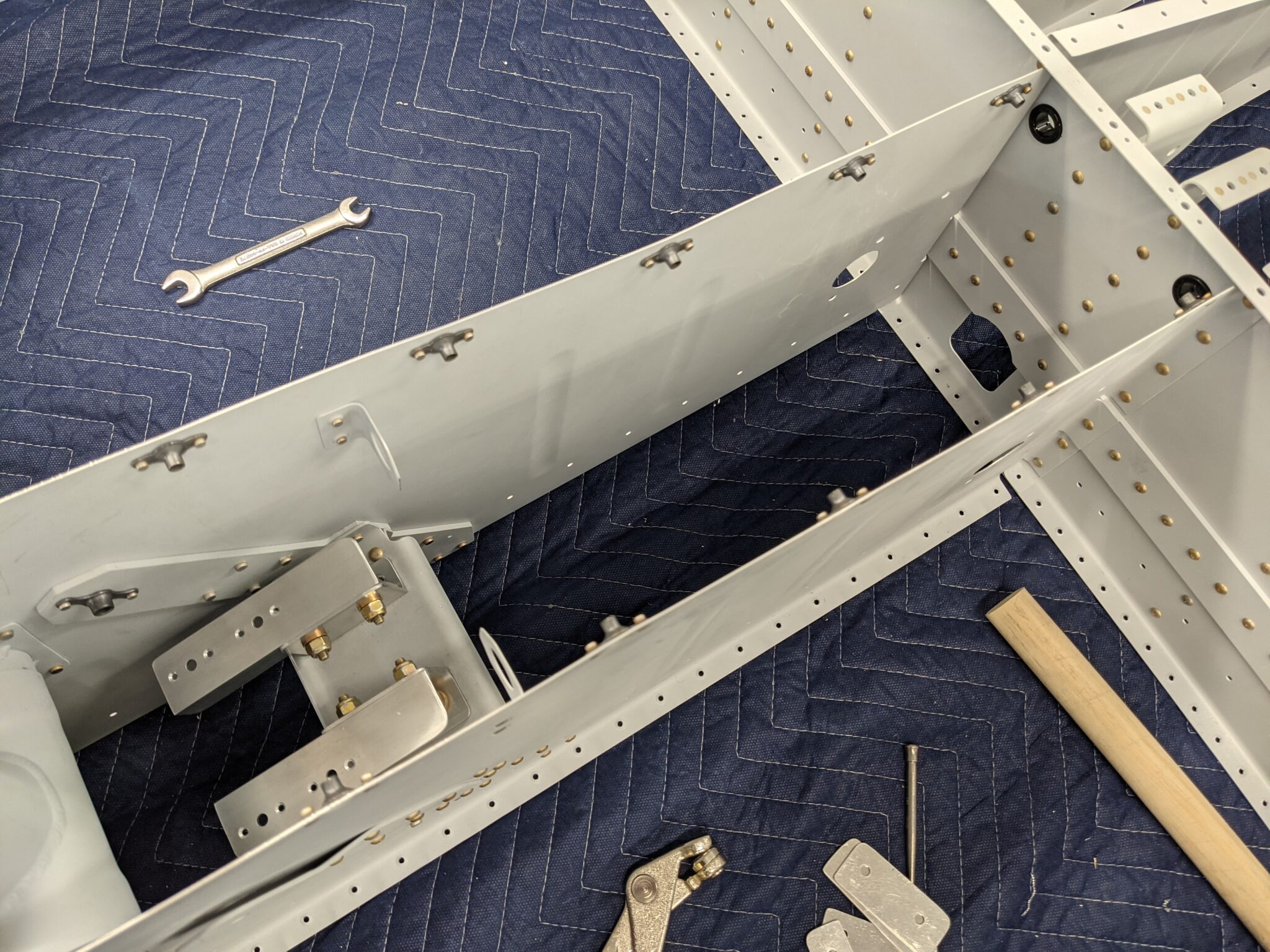
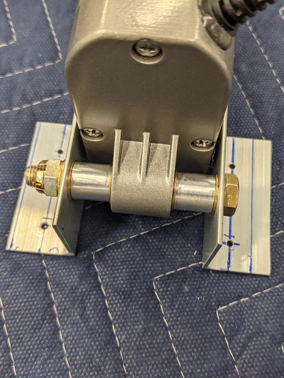
Here are some pictures of the parts before I realized that I had to make spacers. You can also see the material that I removed from the extensions to clear the forward flange on the stock mounting plate.
And with one spacer..
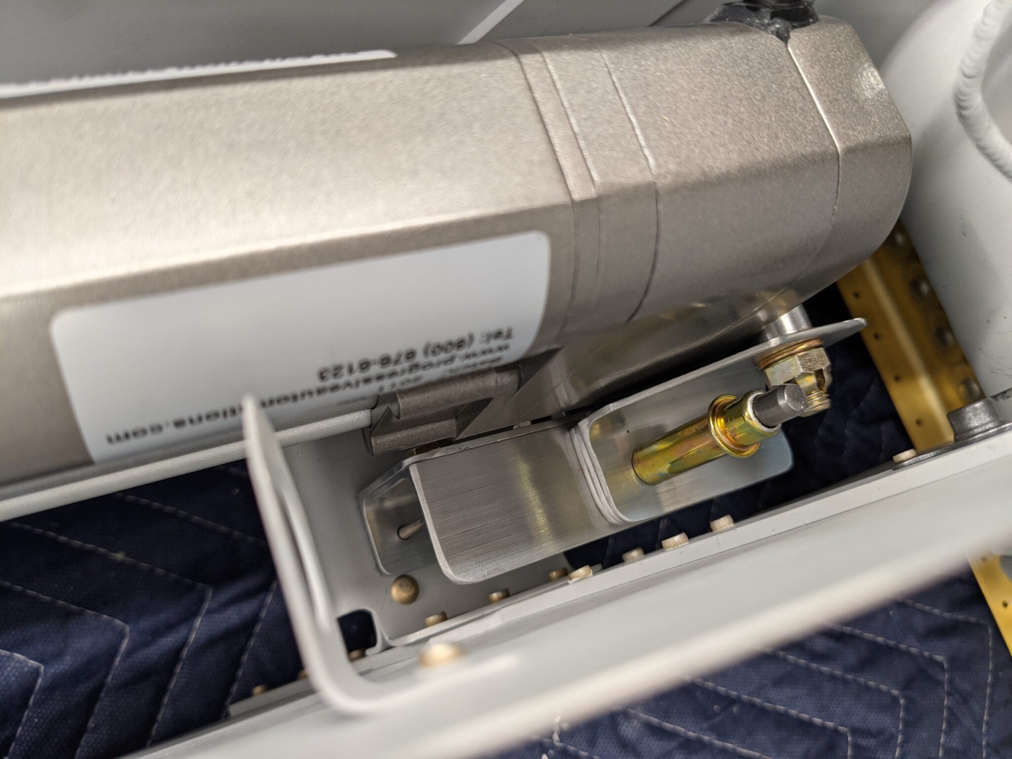
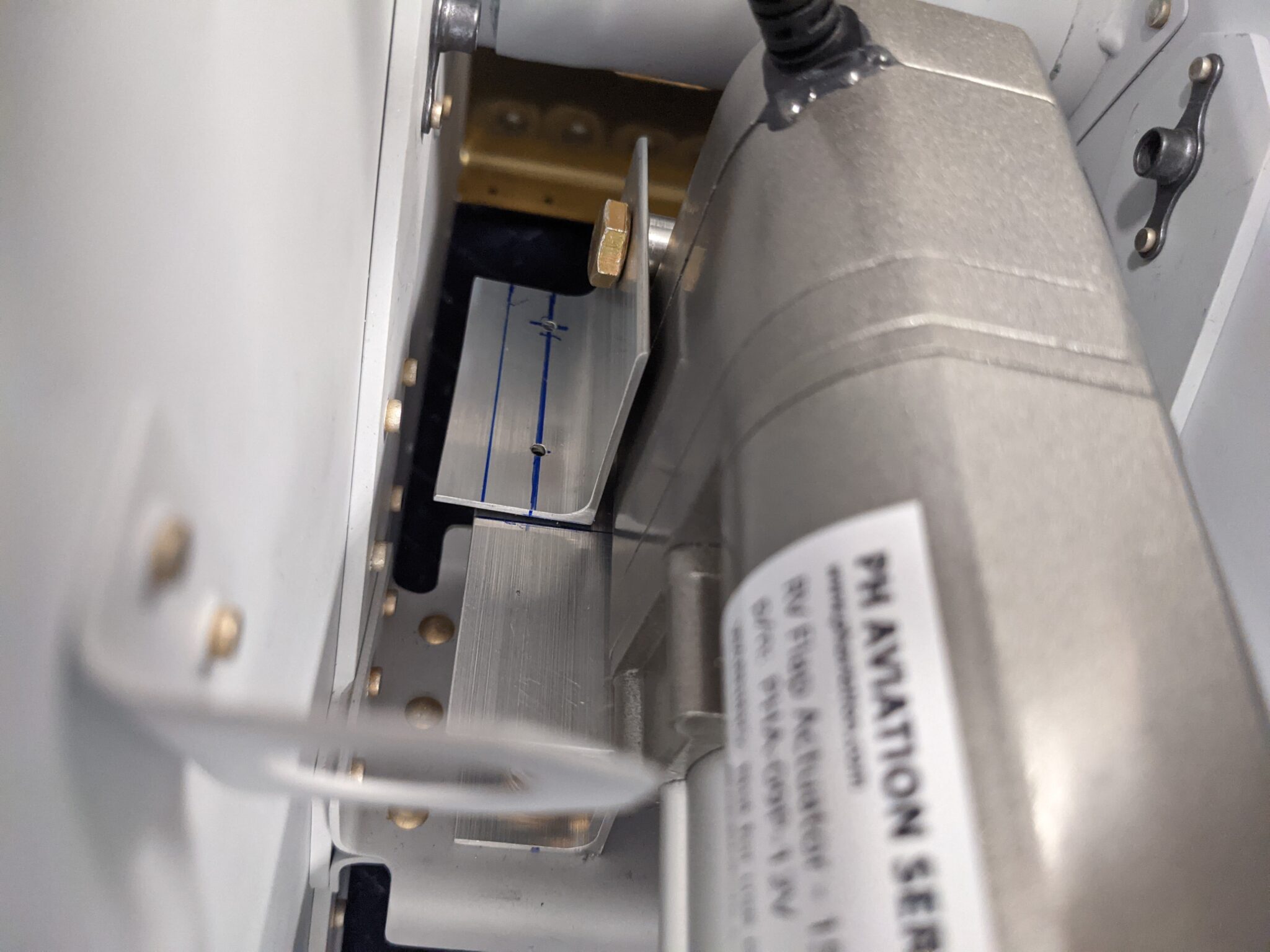
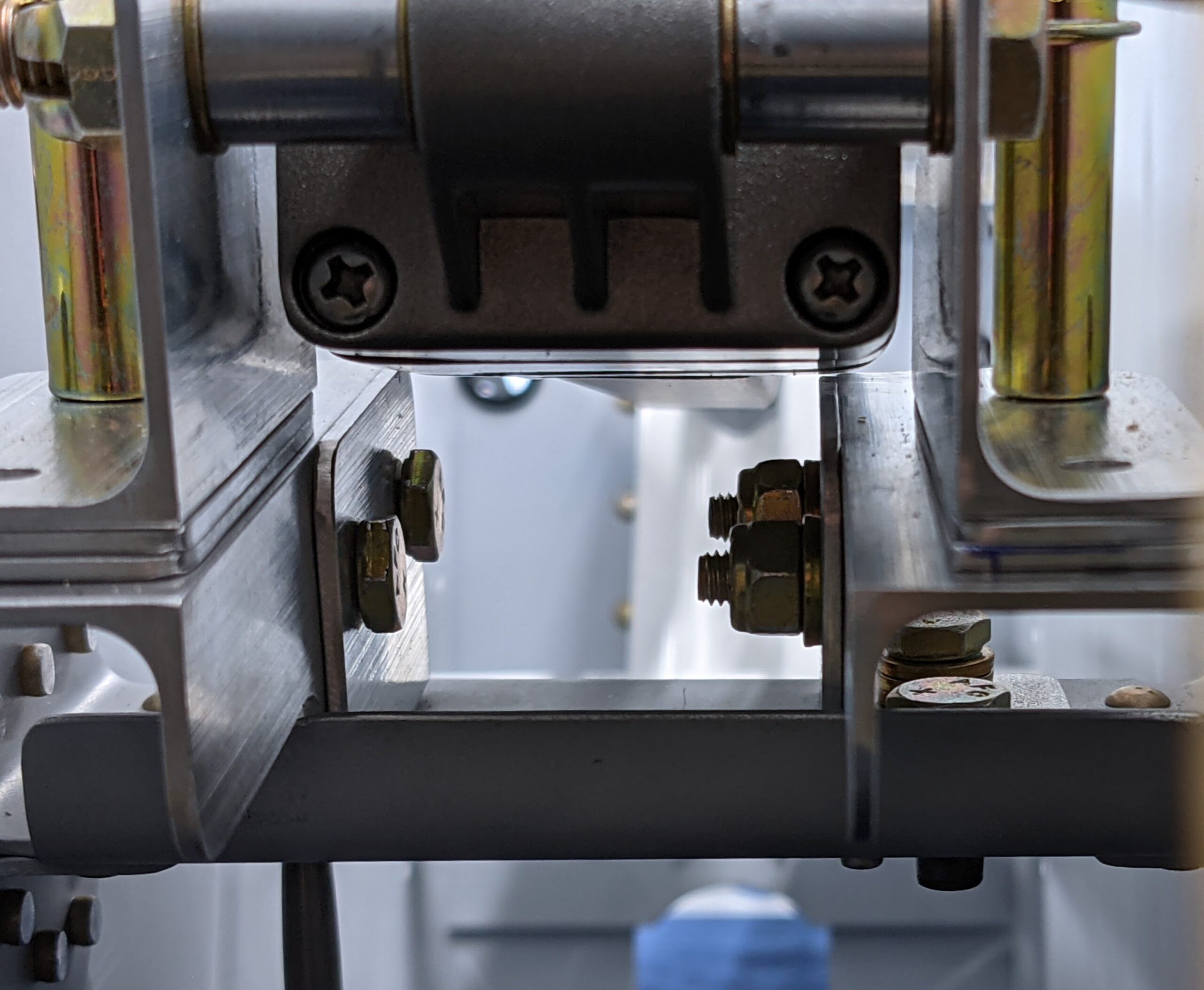
This picture shows the clearance with two spacers at full extension. It is hard to see from this angle but there is a bit less than 1/16″ of clearance on the right bracket with both spacers in place when at full extension.
Here is a clip of the actuator in motion showing the speed of the actuator and the full range of travel.
And a few more pictures..