
I have decided to mount both com antennas under the rear passenger seats. This is a common location and I have spoken with other builders that have found this location to work very well.
An alternative I had considered was to mount one com antenna on the bottom and another on top. A top mounted antenna can potentially improve ground comms. On the other hand, I have seen reports of conflicts with other top mounted antennas that eliminate this advantage. I will also be installing a bottom scoop for AC on the bottom centerline.
I ultimately decided to go with the bottom location described by Justin Twilbeck and I used the measurements that he provided in the linked post to create the doubler plates.
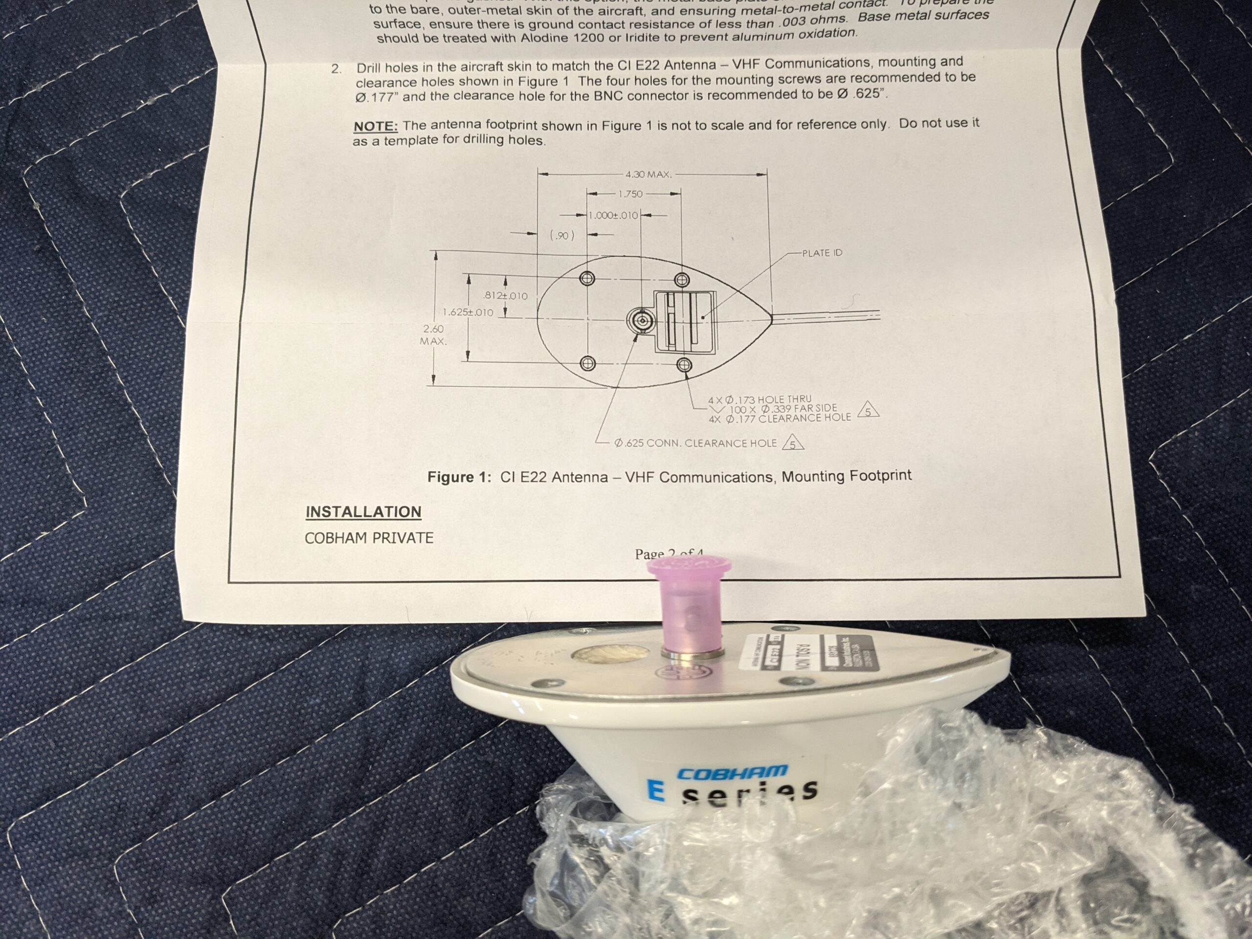
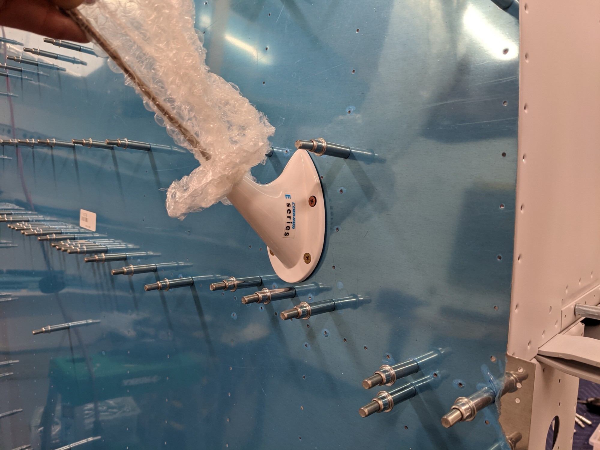
I purchased the Comant E Series version of the bent whip com antennas (CI-E22). As far as I can tell, these are identical to the TSO’d version (CI-122), just much cheaper. I couldn’t find mounting hole specs for the E Series version online but the measurements that came in the box are identical to those for the CI-122 (and identical to Justin’s template).
To simplify the match drilling of the holes, I 3D printed a template using the dimensions from Justin’s diagram.
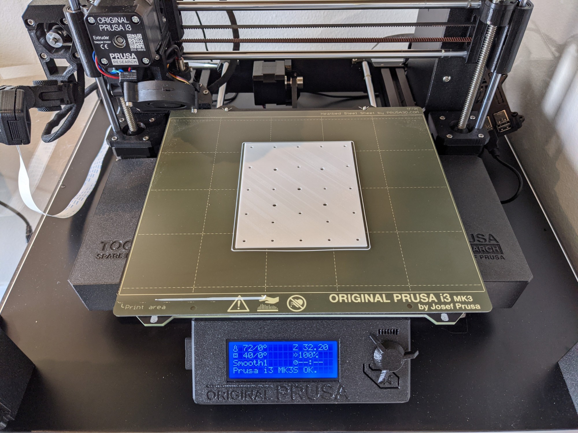
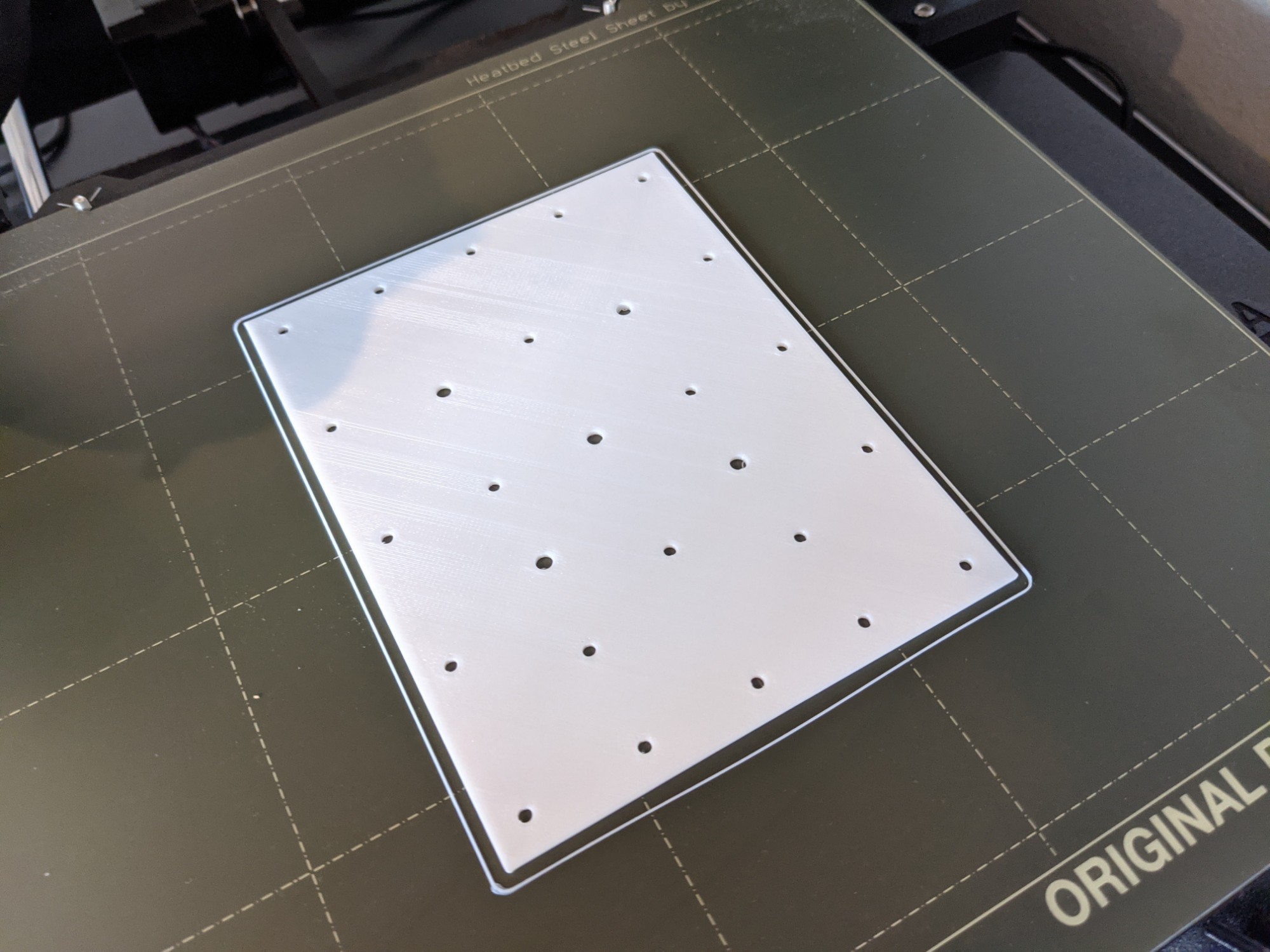
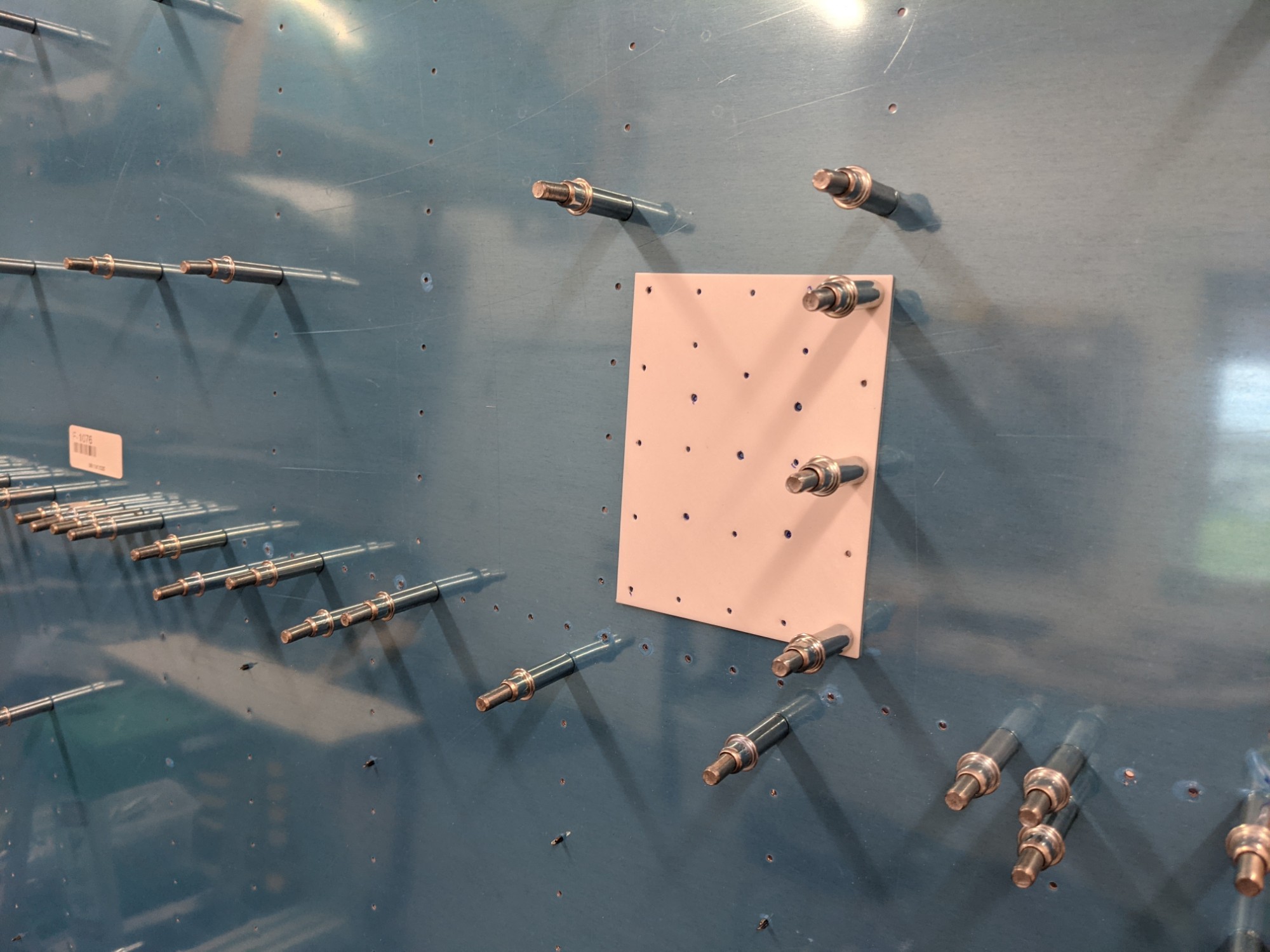
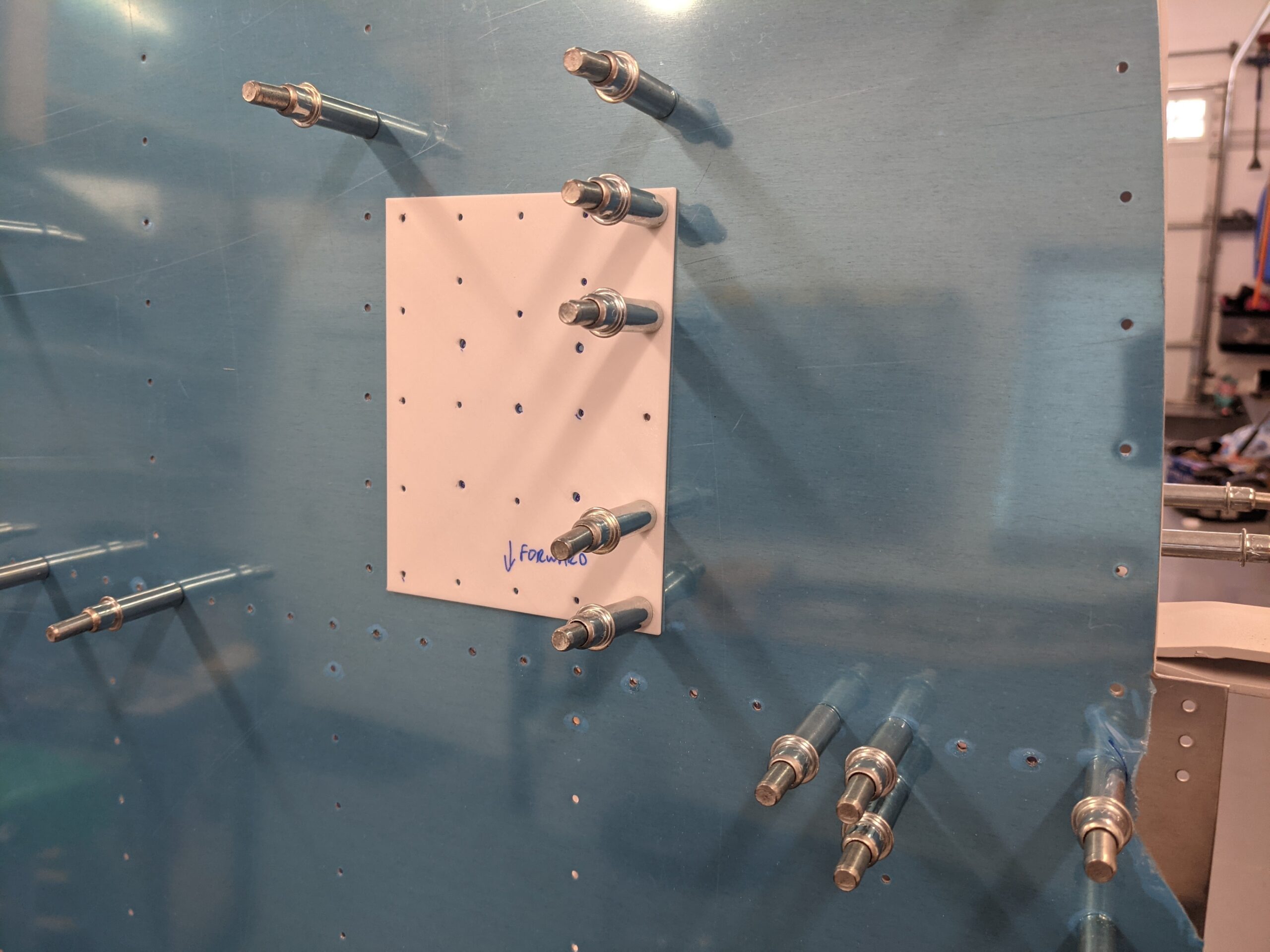
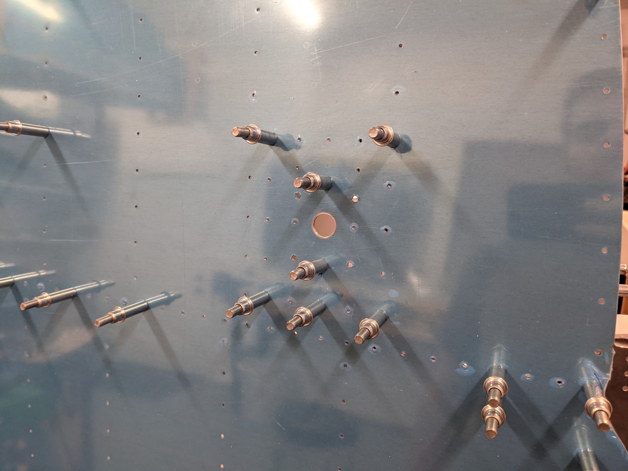
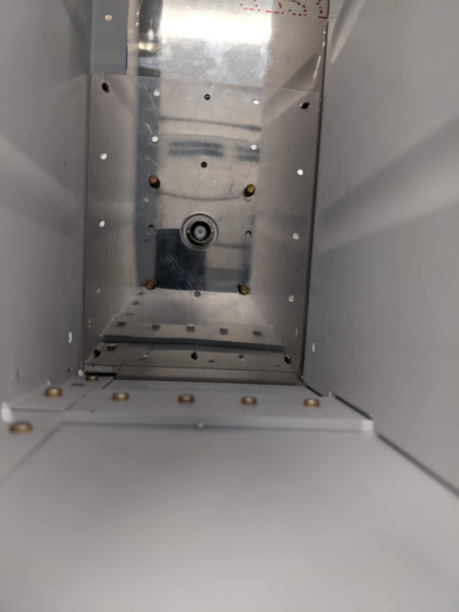
This aligned perfectly with the holes in the bottom skin and seat ribs.
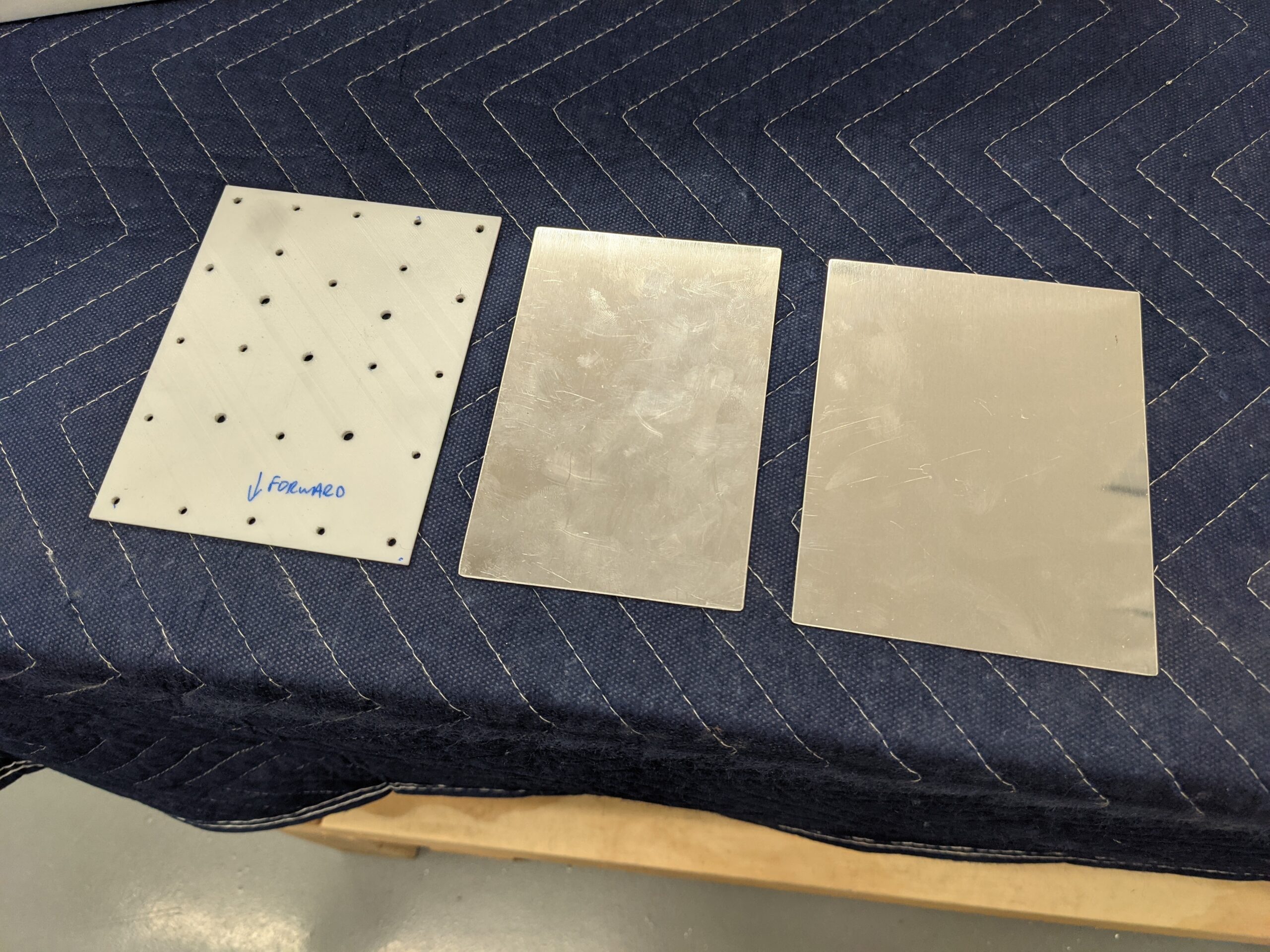
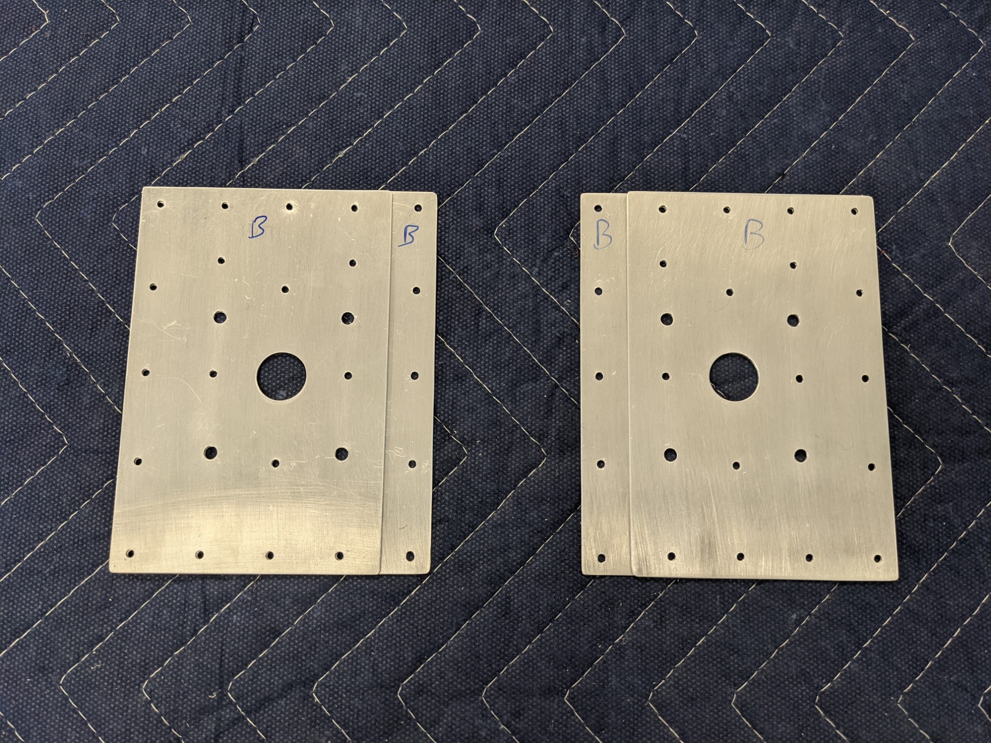
I used the 3D printed template to create a doubler plates and spacers. I used extra 0.025″ aluminum sheet that came with the empennage kit. Thirds were perfect for the length of the doubler plates.
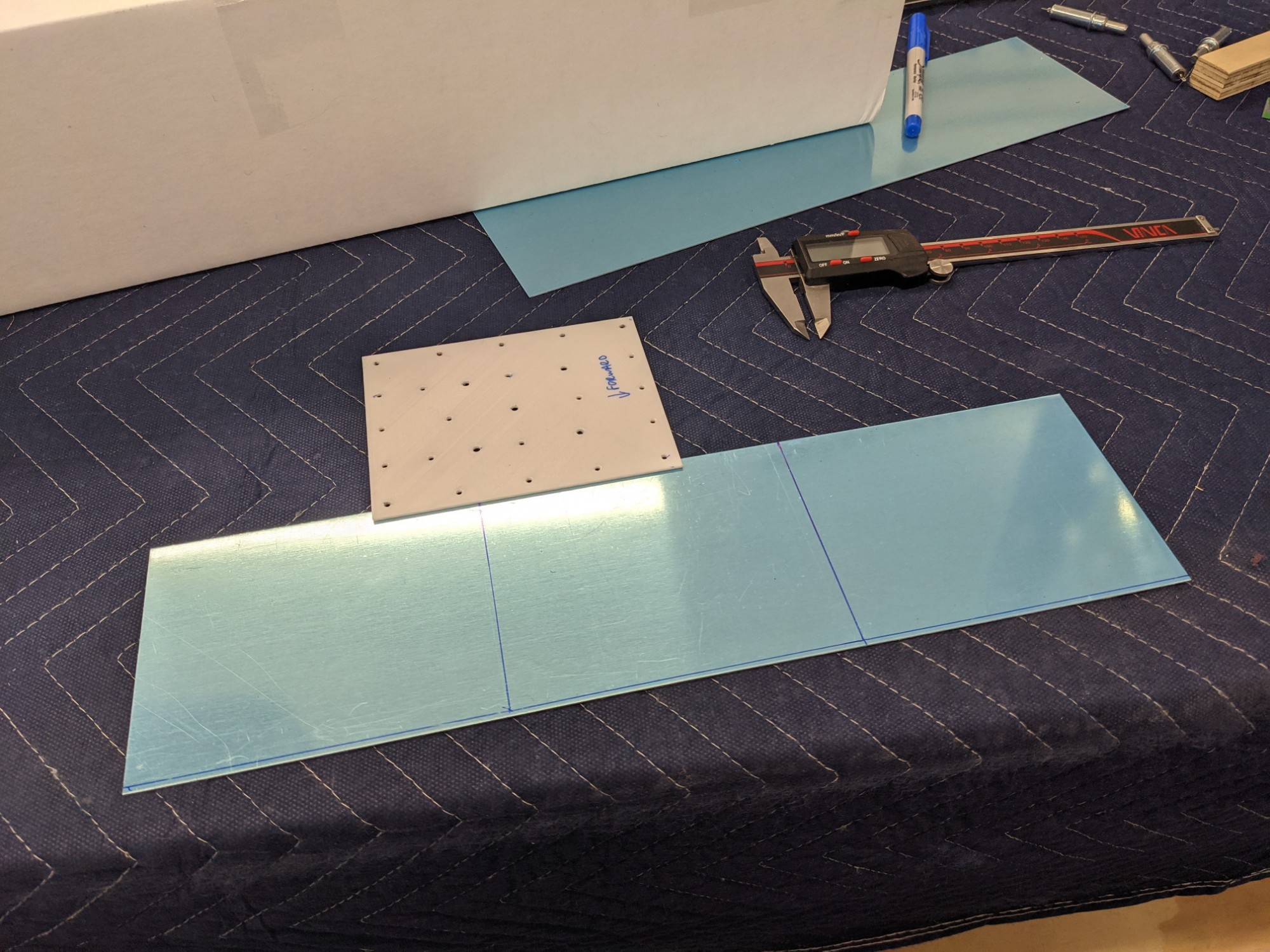
I then trimmed them to the appropriate widths. The doubler overlaps the flange of the seat rib. The spacer is narrower to sit beside the flange of the seat rib.
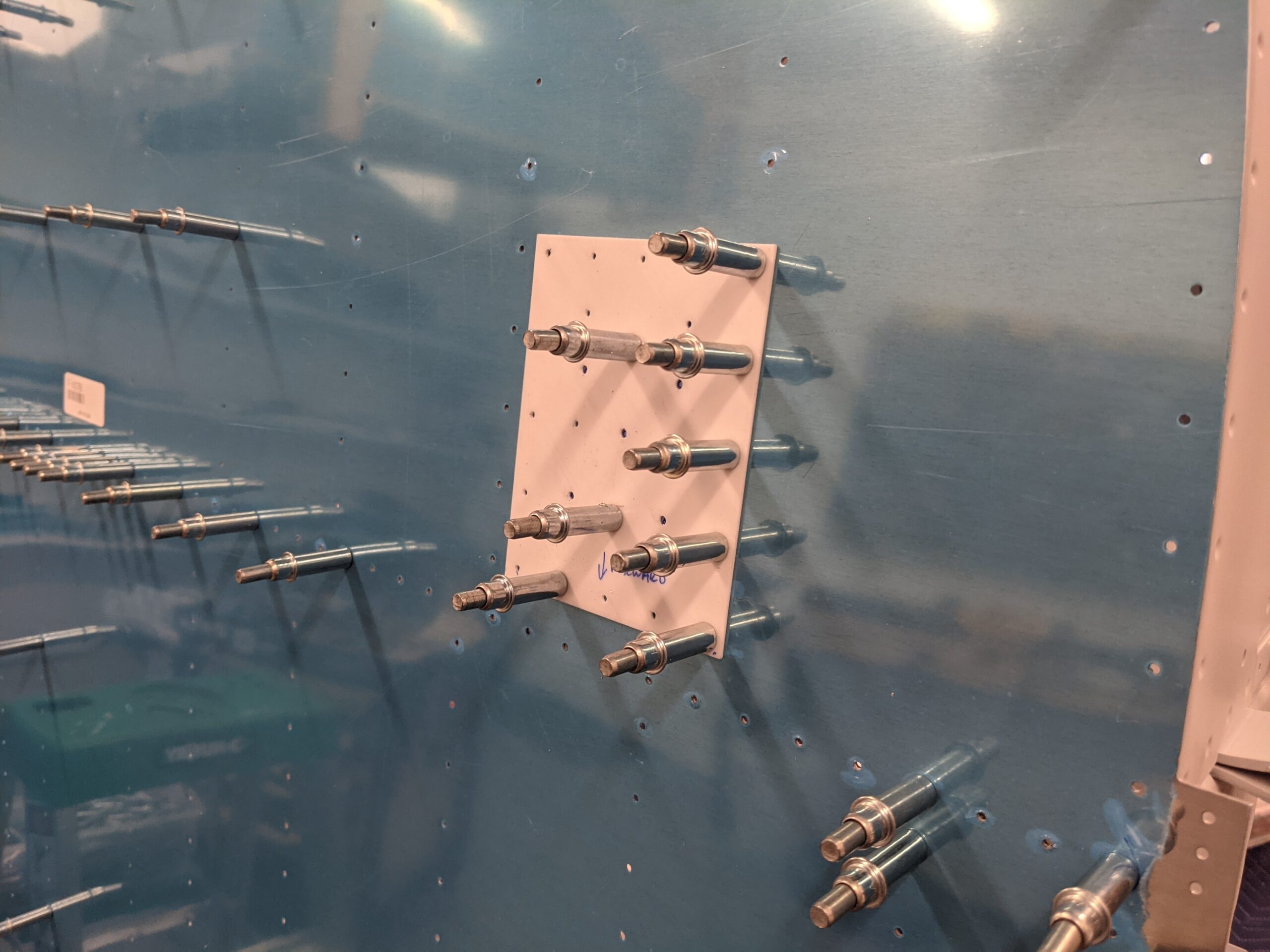
I taped each template, doubler, and spacer together to create two starting alignment holes. I then clecoed the template and doublers to the bottom skin and rib flange. I match-drilled the remaining holes.
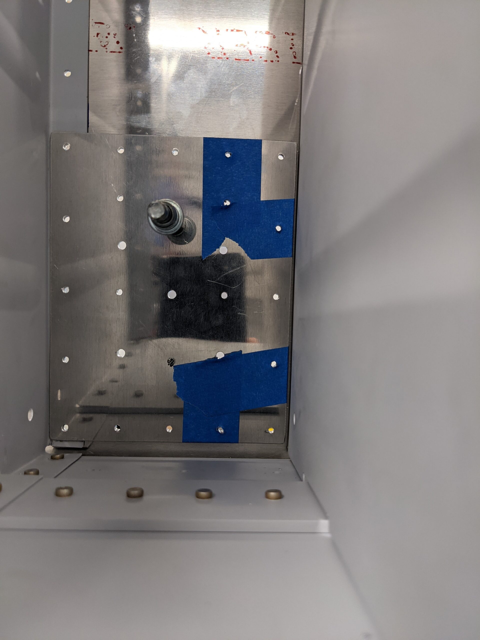
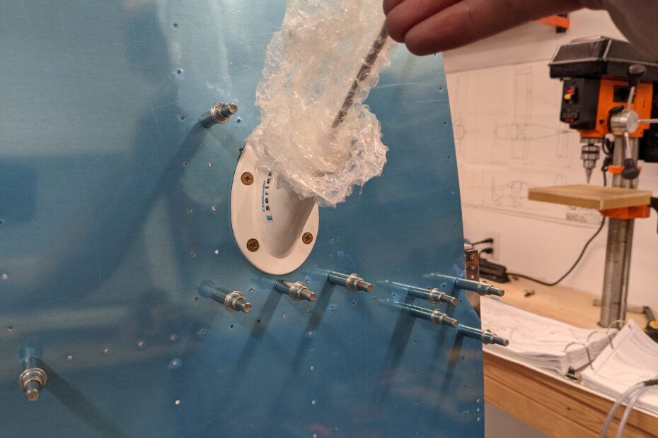
I then upsized the BNC connection hole to 5/8″ per the spec sheet.
The antenna fit perfectly!
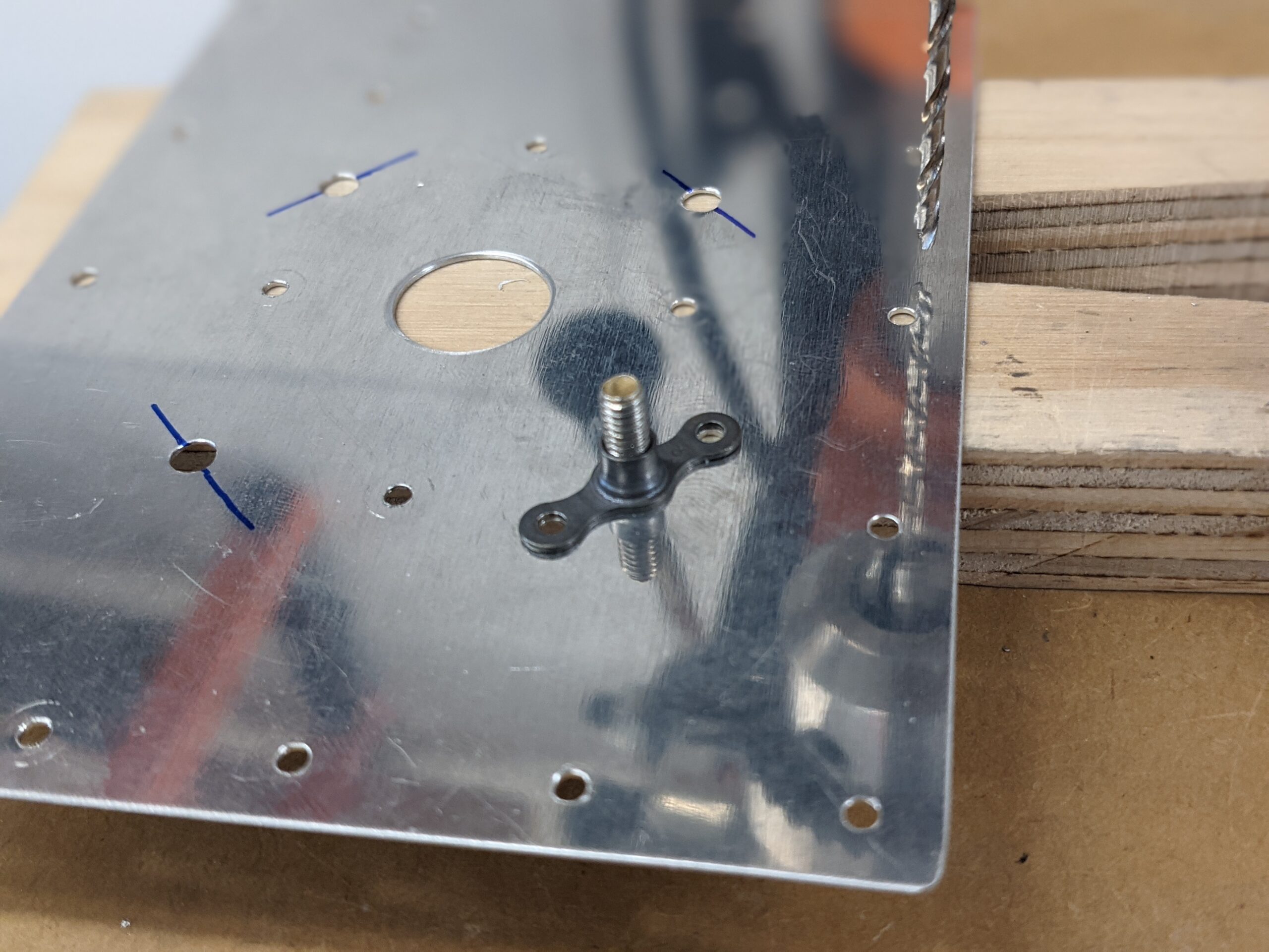
I then deburred the doublers and spacers and marked them so I can put them back in the same place.
I marked locations for nutplates and match drilled the mounting holes. These holes are only made in the doublers. The nutplates will be mounted with flush rivets and the head will be sandwiched between the doubler and the spacer.
I then deburred and dimpled all of the #40 holes as these will be flush riveted via the bottom skin. I’ll dimple the corresponding bottom skin holes when I dimple everything else on the bottom skin.
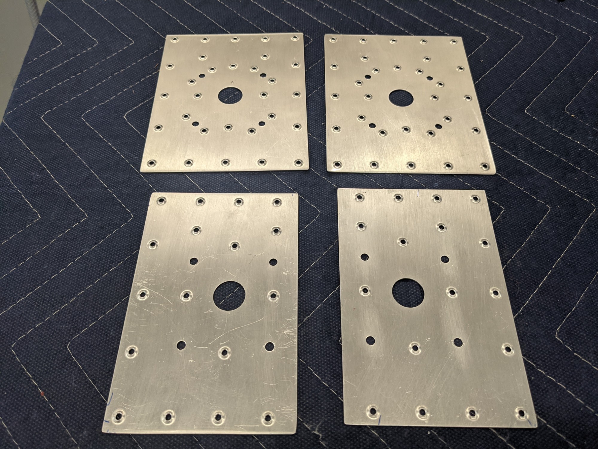
I outlined the doubler locations on the inside of the skin. I will use metal-to-metal contact to ground the antenna. The doubler plates and spacers will be alodined (instead of primed) for internal ground contact. I’ll alodine this area and mask it off before priming.
Success! Much easier to do this now than later.