
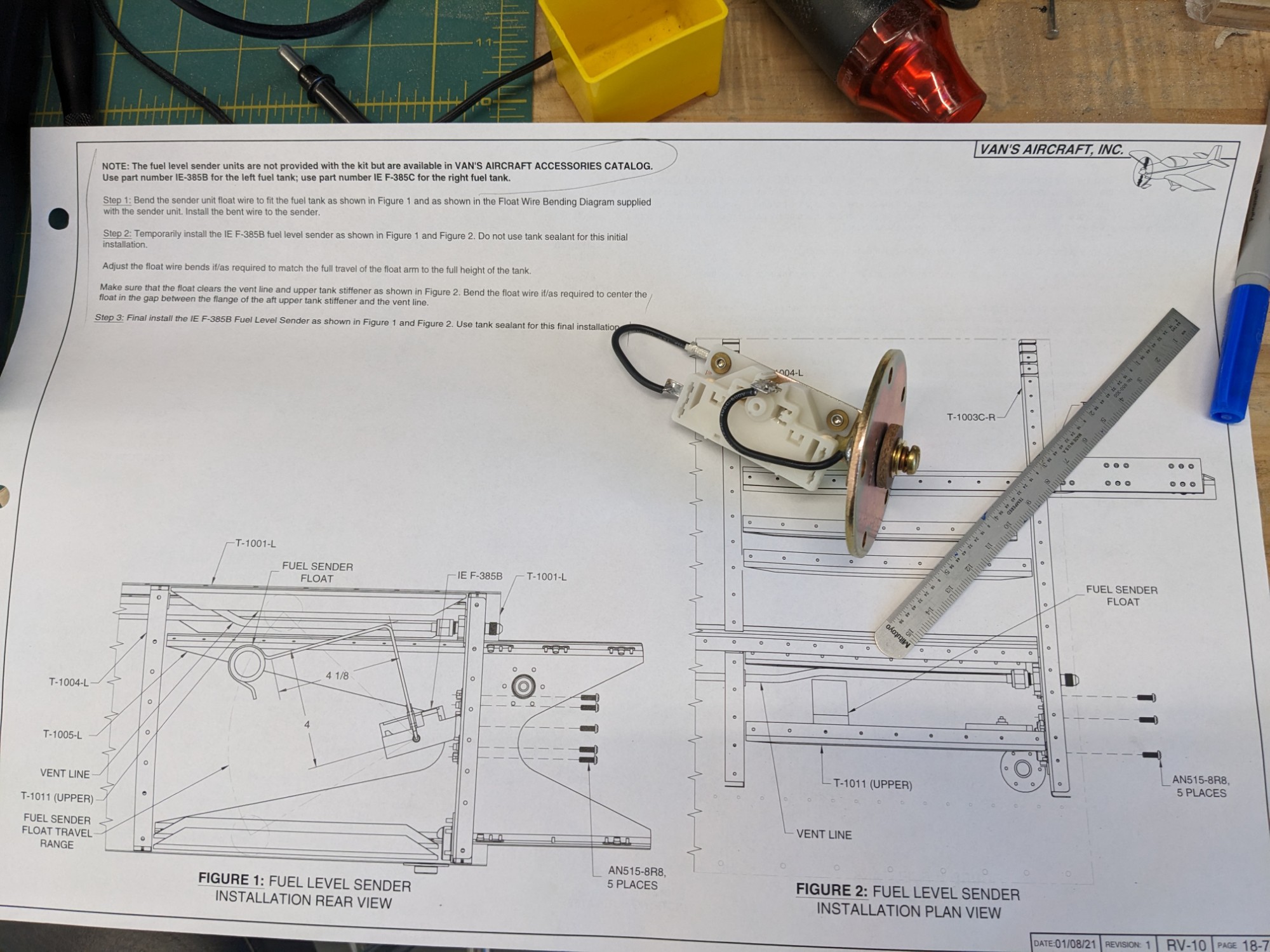
I bent the fuel sender arms per the measurements in the plans and test-fit them into the quick-build tanks.
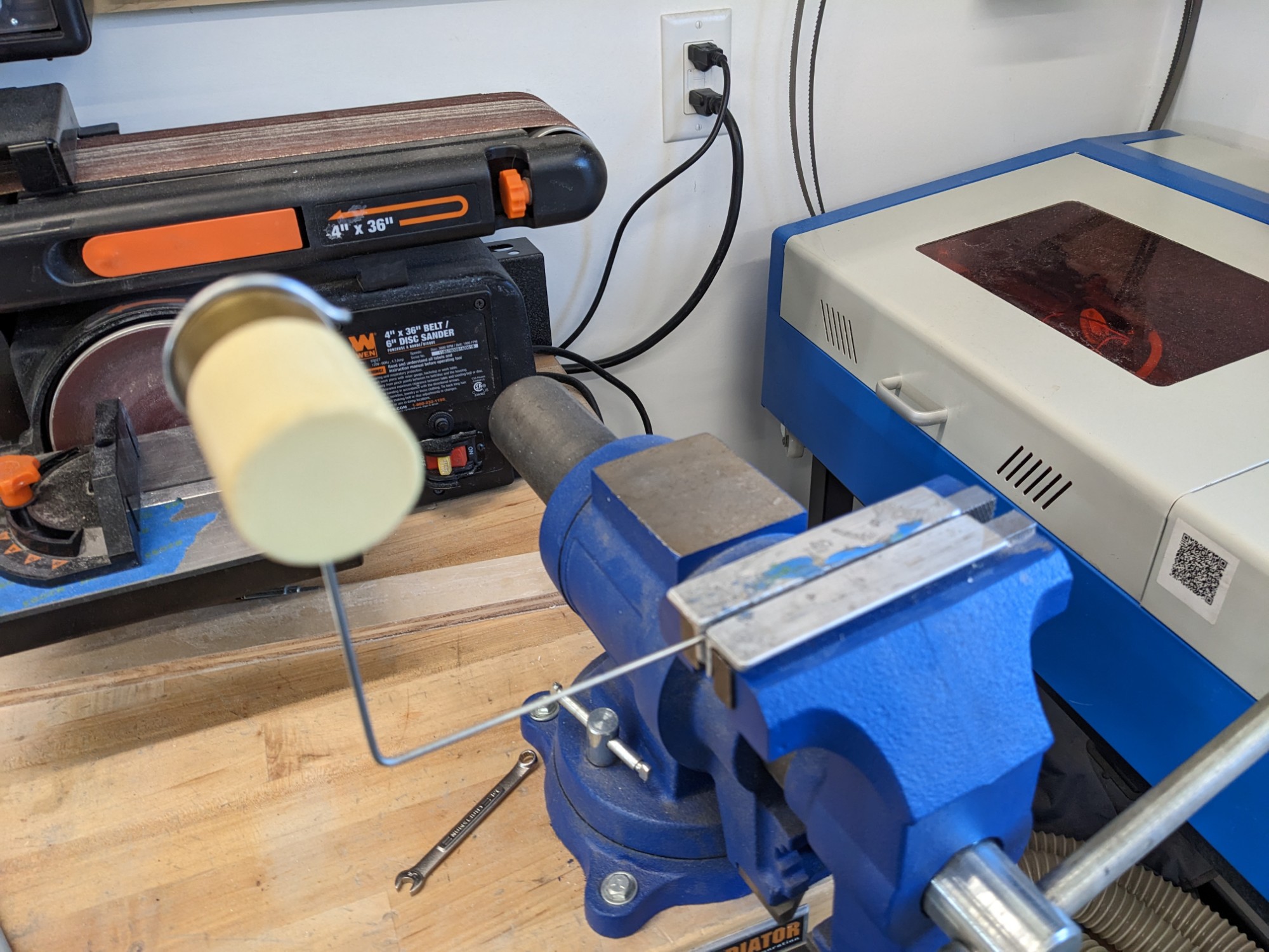
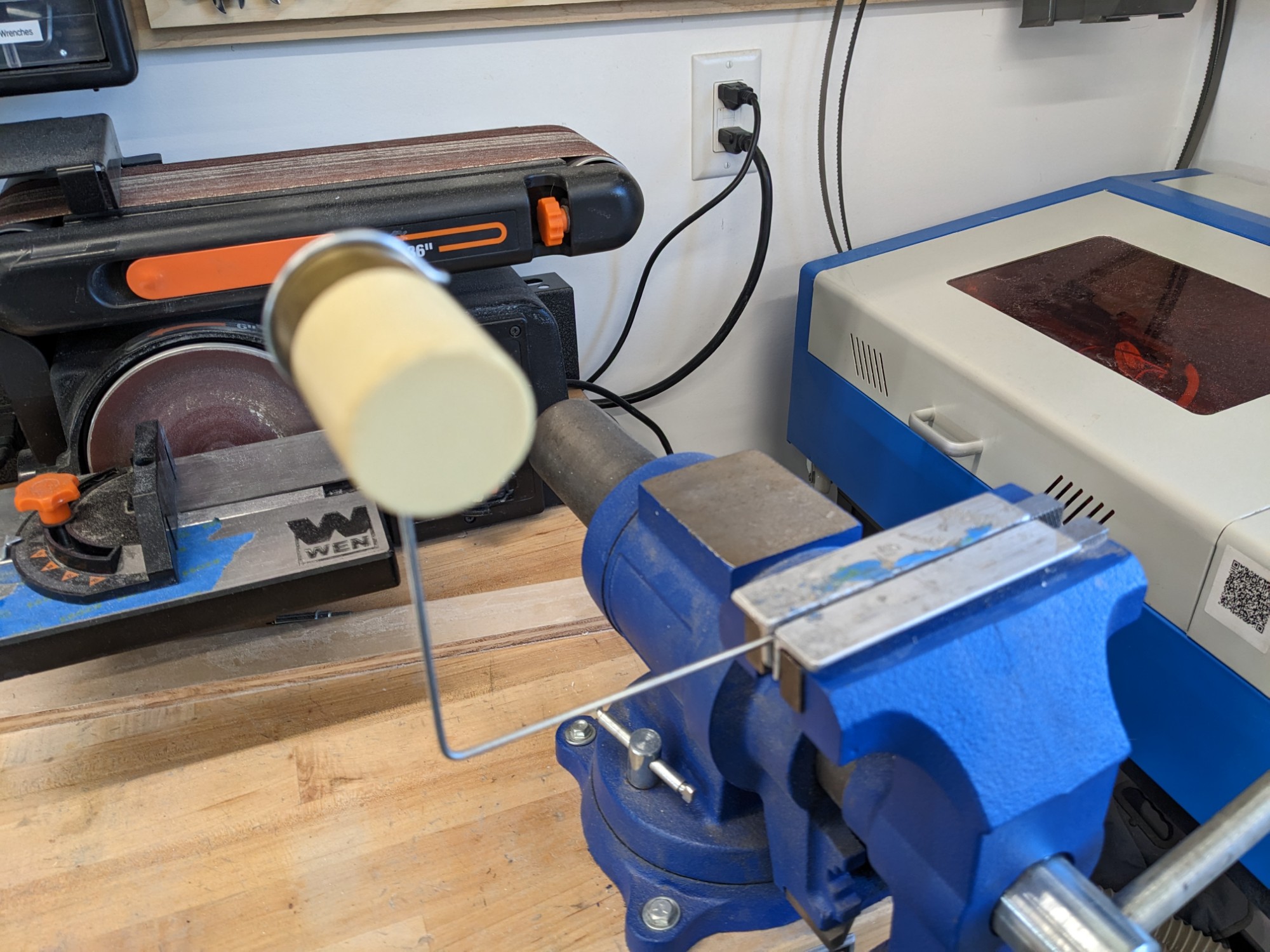
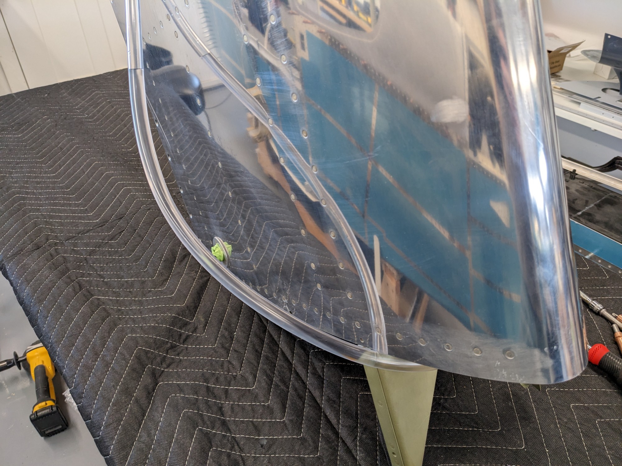
The fuel vent line in the left tank wasn’t bent precisely like the right tank and it left minimal clearance for the float. I increased the bend in the vent line by using a PVC pipe through the sender hole.
I attached a hose to the vent line and I partially filled it with water (with the tank upright) to test the internal vent fittings for leaks. Others have reported leaks here in quick-build tanks that are not evident until fuel starts seeping out the vent with full tanks. This would be challenging to tighten at that point so I wanted to confirm that there were no obvious issues before sealing up the tanks. Both fittings remained dry during testing.
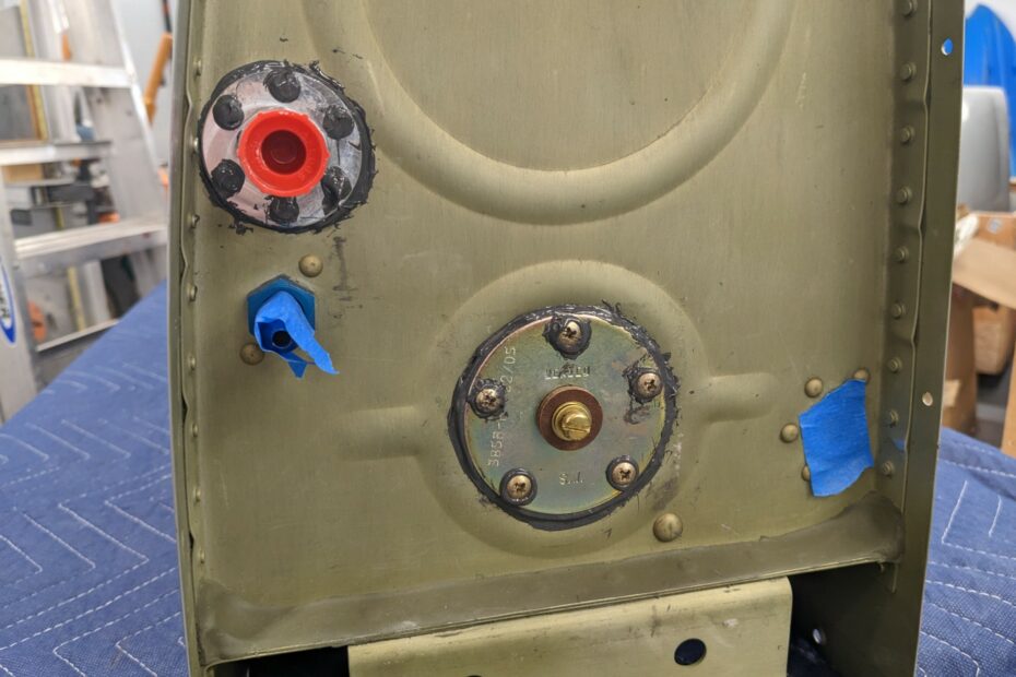
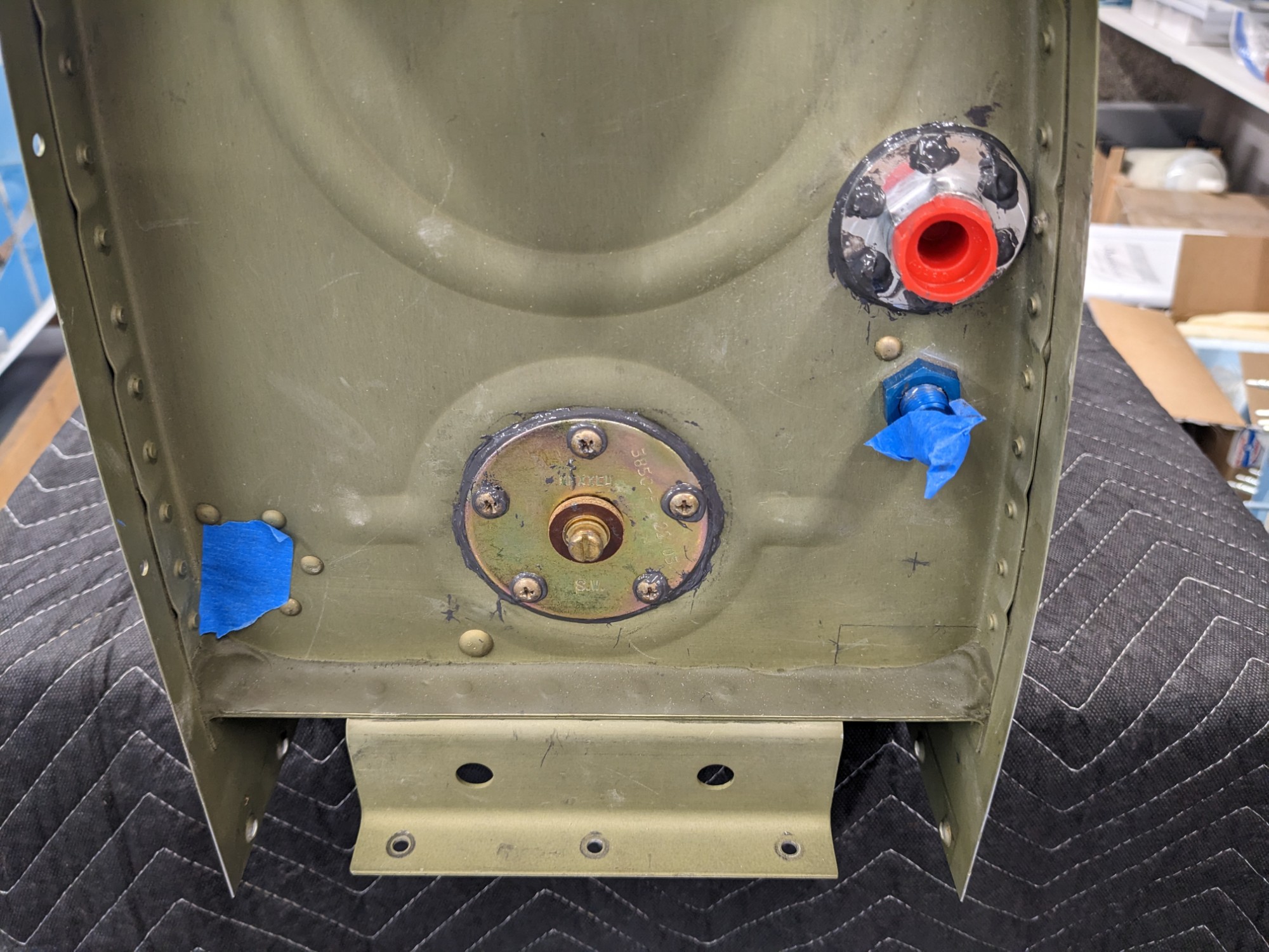
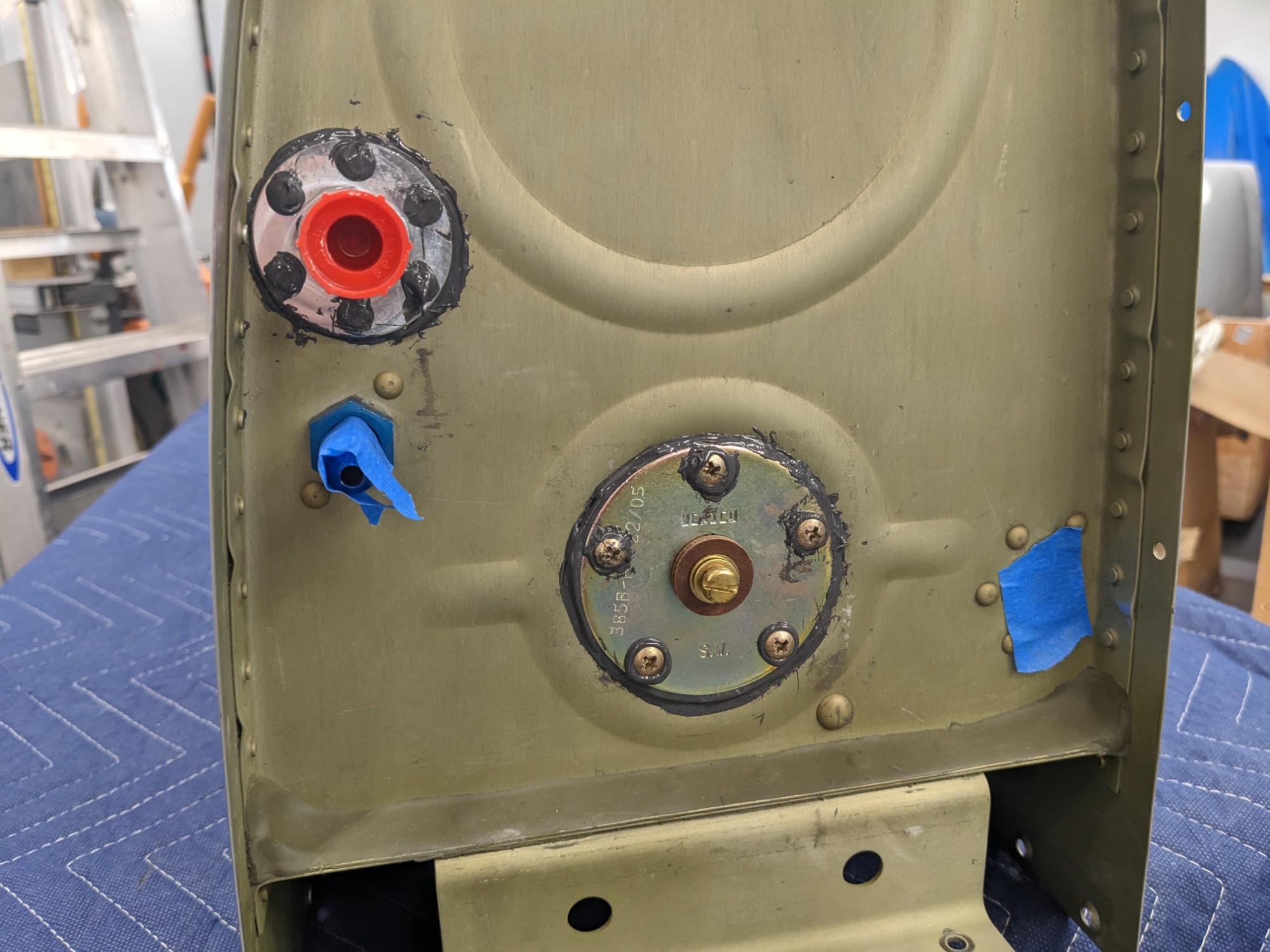
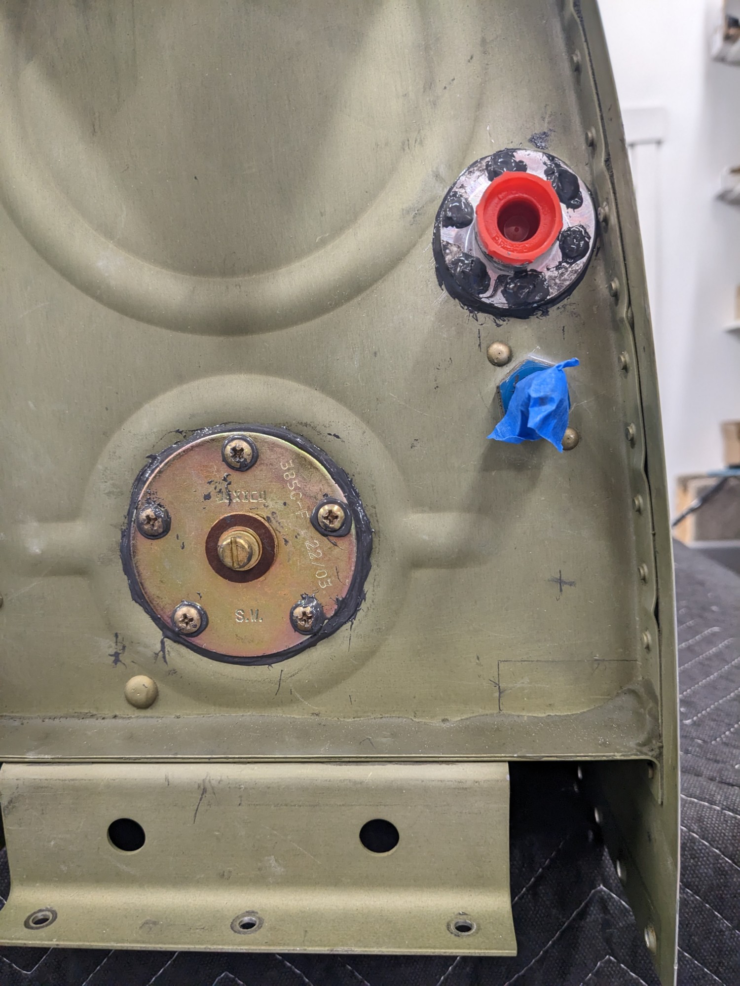
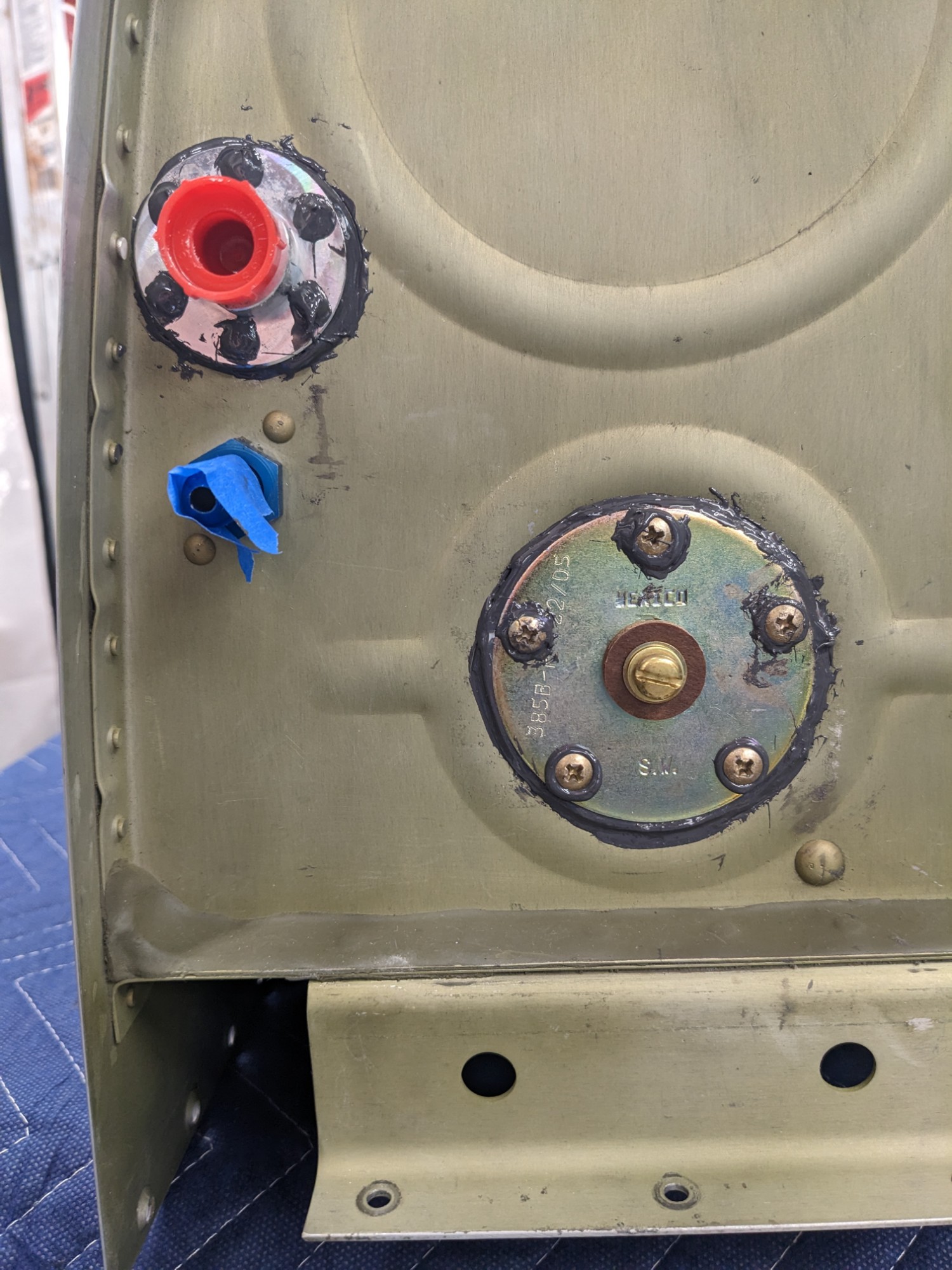
I then mixed up proseal and attached the fuel bungs and stock Van’s senders. I used sealed blind rivets for the fuel bungs (instead of the sheet metal screws provided with the bungs).
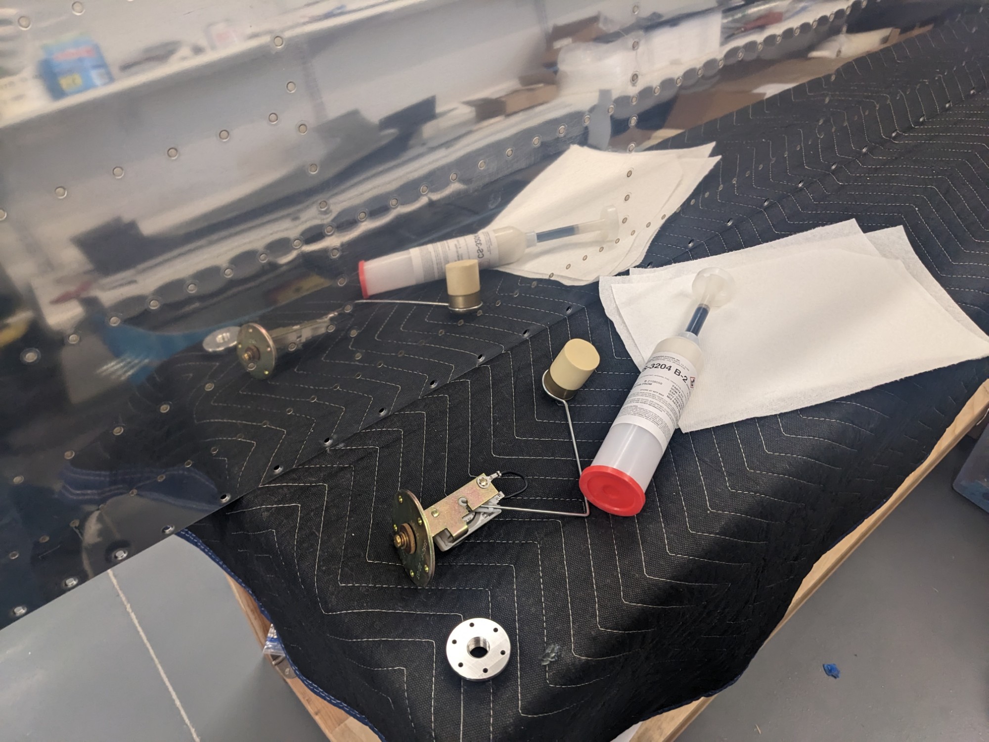
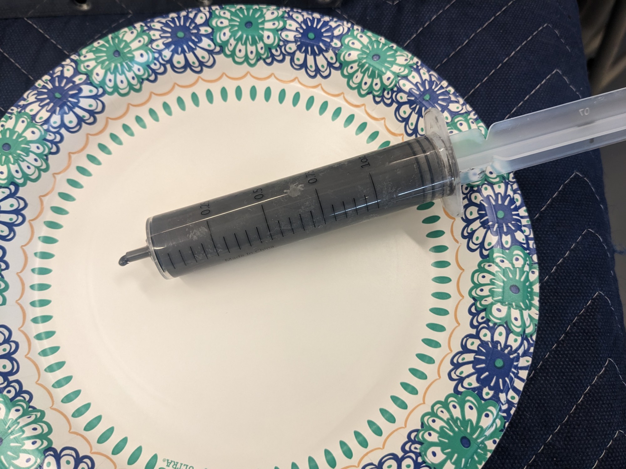
I used a syringe to apply the proseal which helped limit the mess.
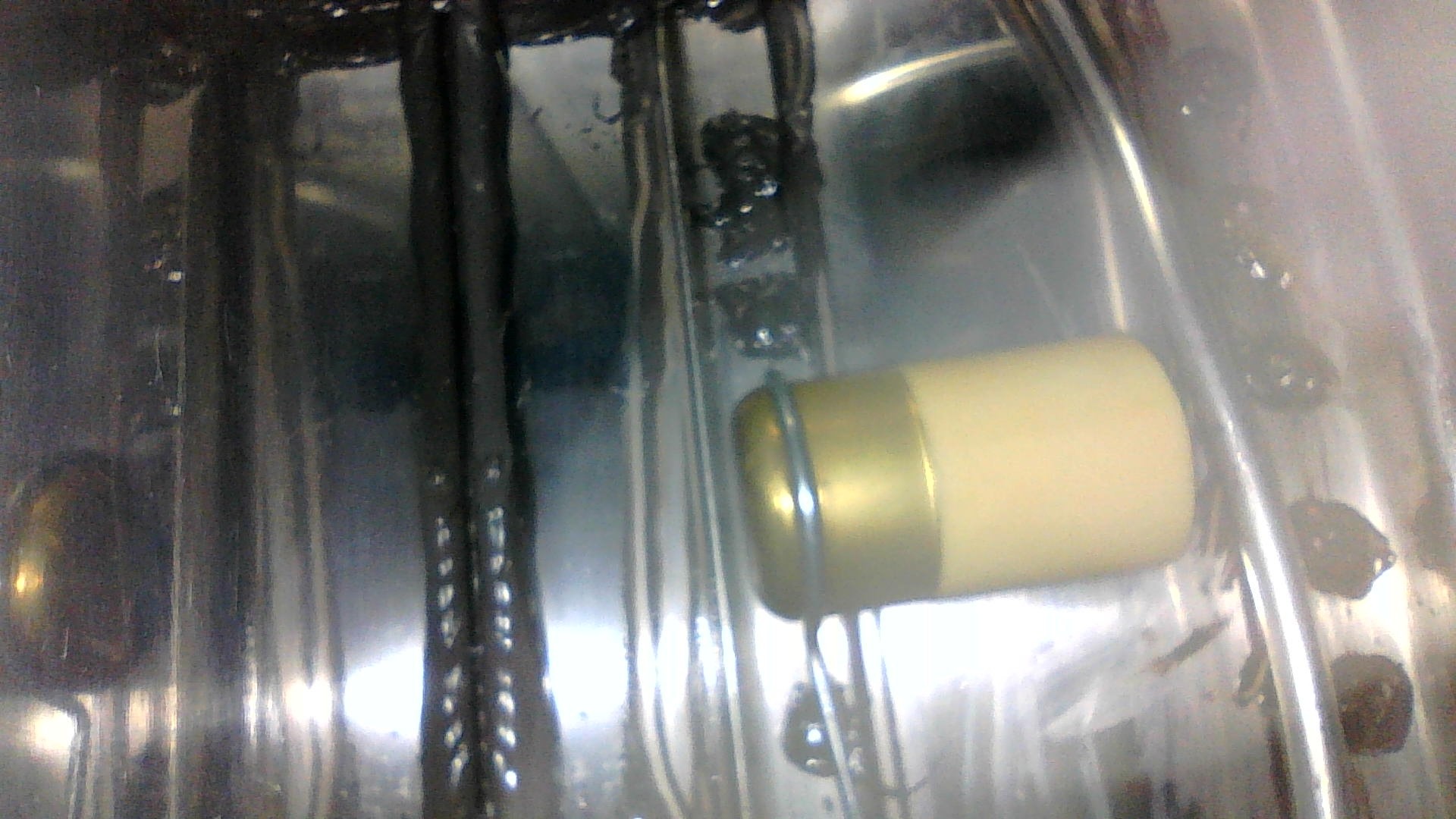
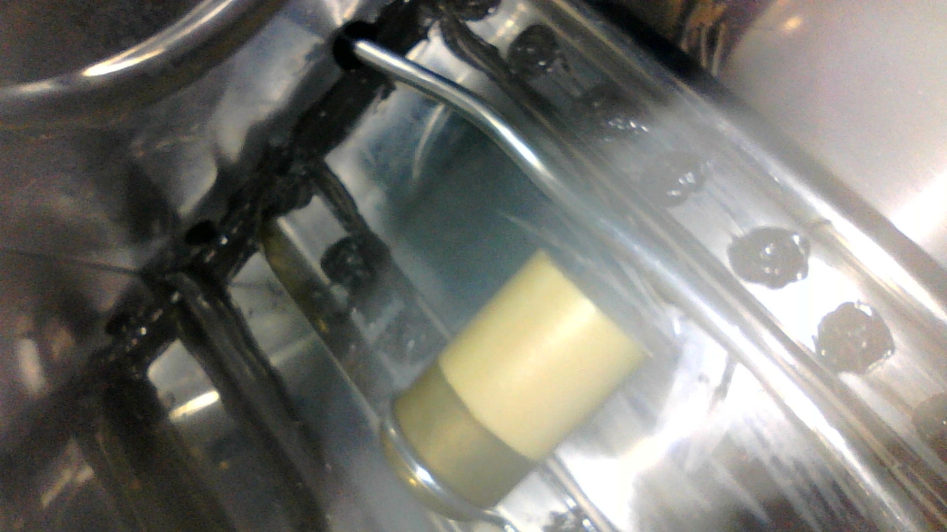
I then double-checked the clearance of the floats with a borescope before leaving the proseal to cure.
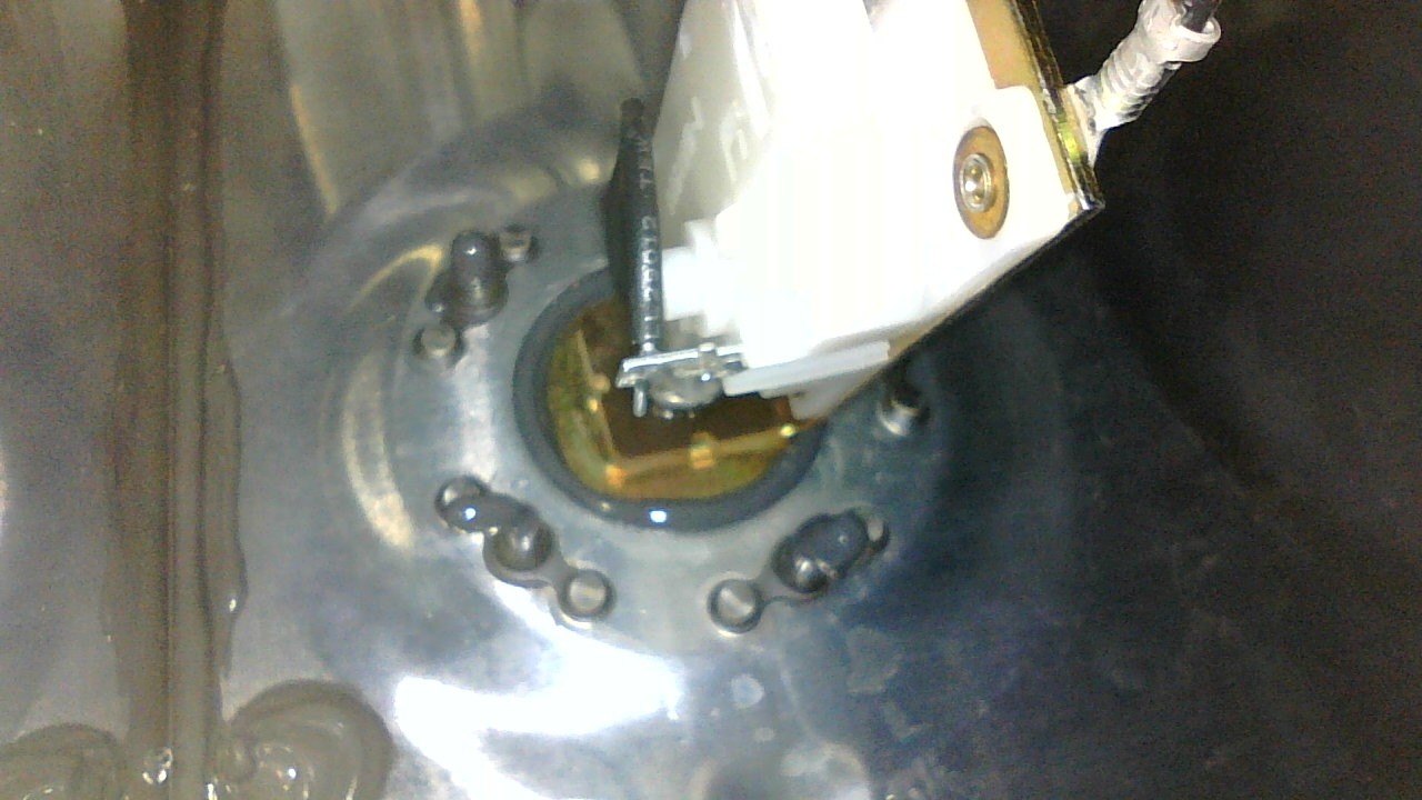
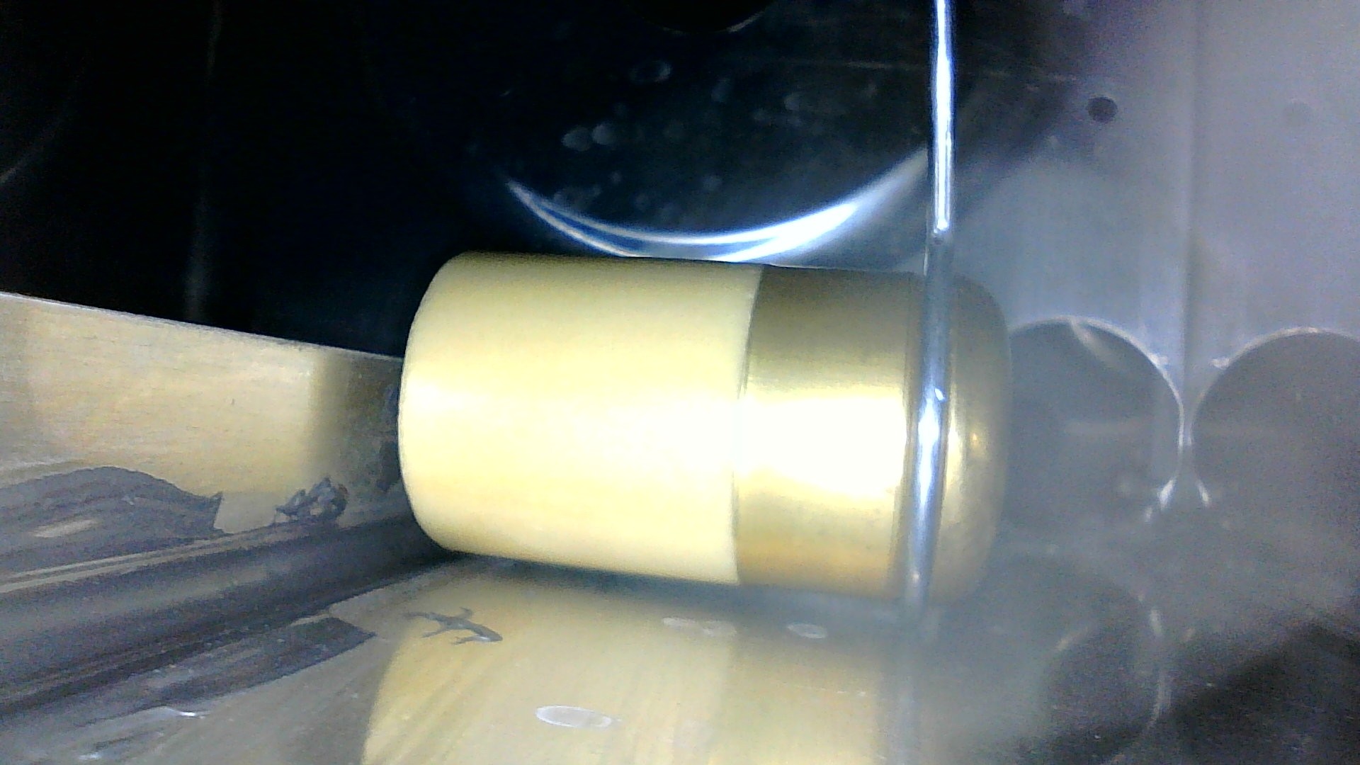
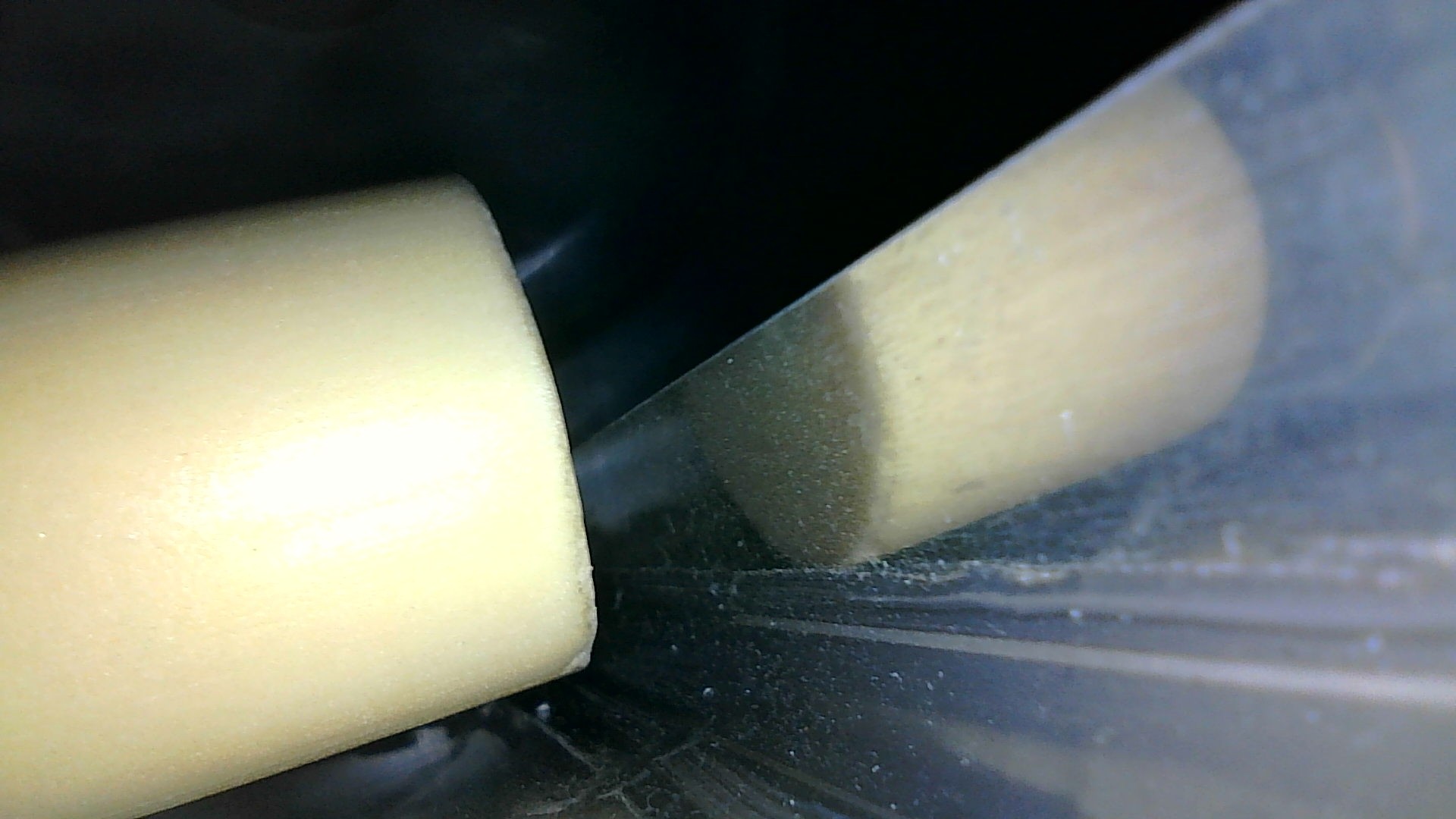
The floats moved through the full range of motion on both tanks.
I measured the resistance range with a multimeter, resulting in the following values.
| Left Tank | Right Tank | |
| Full | 34.6 Ω | 30.5 Ω |
| Empty | 247.7 Ω | 241.8 Ω |
| Delta | 212.1 Ω | 211.3 Ω |